Created: "June 15, 2015"
UPDATED: "June 23, 2015"
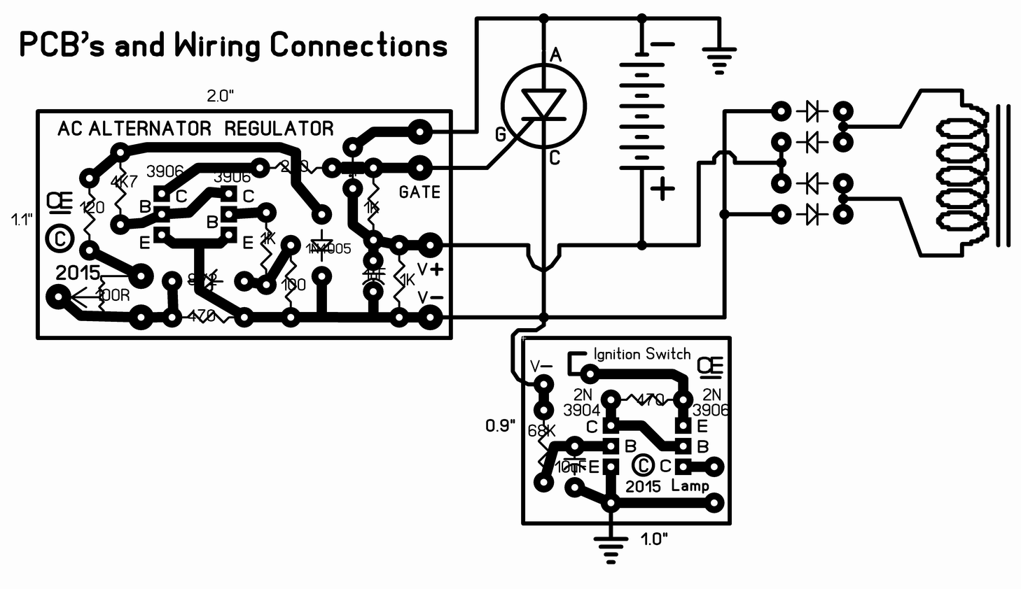
Recently I recieved an Email from a guy in Demmark who has a Ducati Monster Motor Cycle. This Motor Cycle has a Permanent Magnet Alternator that is Really Bad for burning out the Voltage Regulator. He says this regulator is also quite Expensive to replace. So he Asked me for Help to create a BETTER REGULATOR. The Origional Regulator is Potted in Epoxy and he has not been able to get it apart to see how it was made or to try and repair it. I was told this Alternator puts out 16 Amps Maximum, And the Output Voltage is: 35 Volts AC at 1500 RPM, 70 Volts AC at 3000 RPM. and 105 Volts AC at 4500 RPM. This is a LOT of Power to Control. This alternator has ONLY an Output Winding, So unlike conventional car alternators, their is No possible Direct Feedback to control the output voltage. Based on the High AC Voltage Output of this alternator and the Much Lower Regulated DC Voltage that is required, A conventional Linear Regulator is Not Practical. So my approach is to use an SCR to create a Pulsed Output, switching the SCR On and Off to maintan an "Average Output" of about 14.4 Volts. I also added a circuit for an Alternator Indicator. It lights up a small light bulb if the regulator Fails. At this time, This circuit has only been BENCH TESTED:If Built and Setup Correctly, This circuit should regulate the Charge Voltage at the correct voltage. (Typically 14.4 volts.) This Regulator Can't be used as a Power Supply, Without having a battery in place. The Battery MUST be Connected to get Correct power output.Because there is No Current limiting on the alternator, A suitable In-Line fuse is Definately Advisable. So if the battery should develope a problem and try to draw Excessive Current, the fuse will blow and protect the Stator winding.
Some Additional Notes:
There is No Amp-Meter shown, But I would Definately recommend including one in either the positive or negative line, going to the battery.
The Diodes and SCR, Must be capable of handling the output current. Allow youself a Safety margin! Use a Minimum, 20 Amp Bridge Rectifier and SCR. The "Bridge Rectifier" and "SCR" will Definately require a Suitable, LARGE Heat Sink on each one!
The 100 ohm trimpot on the PCB sets the Maximum Charge Voltage. To set this Correctly, Attach a Fully charged battery to the output. Than using a meter to monitor the output,Set the trimpot to give an output of 14.4 volts at Very Near ZERO CURRENT.
"Back to My Projects Page"
"A Picture of this Field Winding"
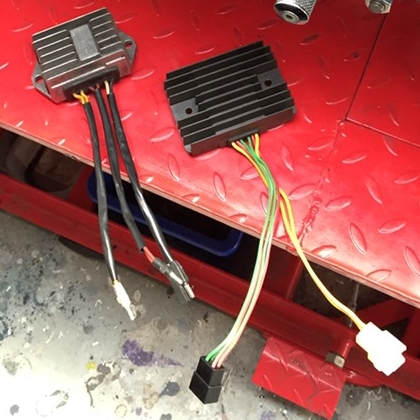
"A Picture of the Origional Regulator"
All Imformation in this Article is "Copyright protected".
Chemelec
*Copyright © 2015*