Doug's Alternator Regulator
Created "Nov 9, 2012"
Doug had a Regulator Problem, So he built up my Regulator circuit.
Doug's Email:
Everything your looking at was my design(except your regulator). I made all of it.
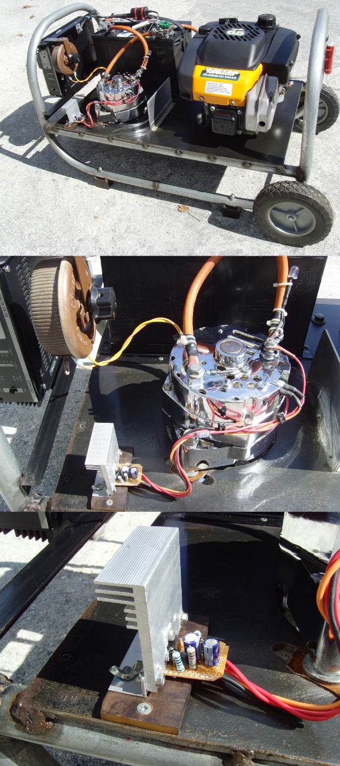
It is a great inverter generator setup.
You can see the red wires coming out of the alternator feeding your voltage regulator circuit which is mounted to the
steel deck with aluminum angle and bakelite to isolate the positive heat sink from the negative steel frame.
The large control above your circuit is a 10 ohm/4A rheostat.
I use that in series with the rotor coil for charging the battery after I used the inverter without using the
engine to charge the battery.
Normally you would not be able to start up the engine after you drain down the battery to 12-12.2V after using the
inverter due to the battery being low on voltage.
What I do is turn the rheostat up to 10 ohms, then start the engine and slowly decrease the resistance of the rheostat
until I feel it is enough load on the engine.
At that point I let the engine run and charge up the battery.
After it is fully charged, I put the rheostat back to the 0 ohm position. It works great.
Doug
His Previous Email:
Guess what? TOTAL success! I had to increase the value of the 1.5K resistor from the diode trio to 3.2K,
and lowered the 1K to the base of the TIP121 to 820 Ohm. It works great!
I'll send a pic of the completed circuit with the generator I made. I also increased the size of the heat sink.
Doug