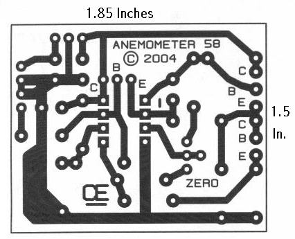
I designed up this circuit board because of a request from a visitor to my website.
I also assemble the circuit board to Varify the board was correct. It does work, VERY NICELY, but I have no way to varify the accuracy of wind flow that is stated by the author.
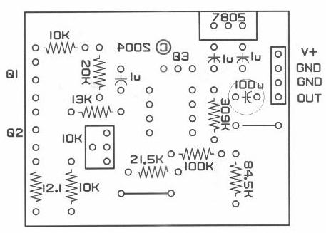
Note: Since the Circuit Requires a Stable Supply, I have added a 5 Volt Regulator to the Circuit Board.
CLick Here, A Link to:
The Author's "Write-up and Circuit"
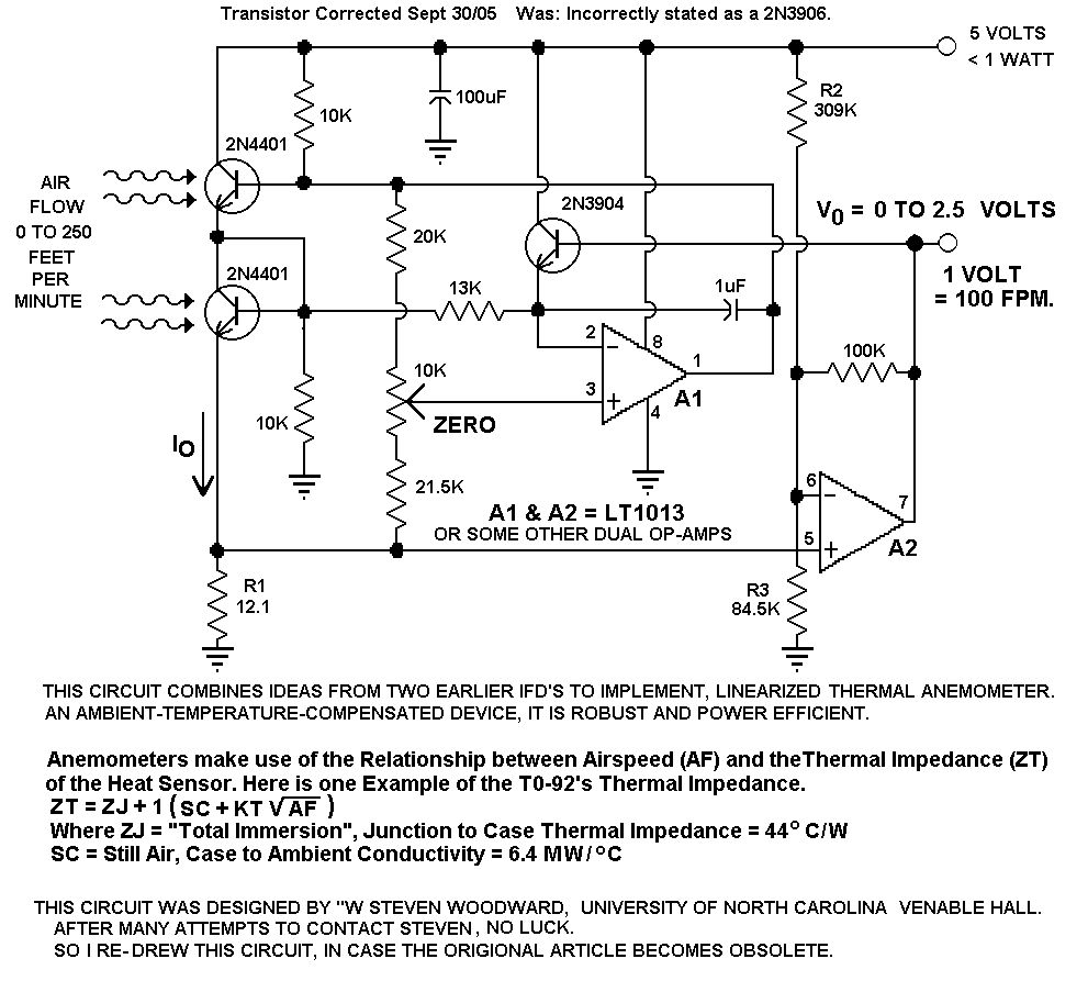
Some of This Authors Design info and formulas are a bit confusing to me.
So, Feedback Wanted: If someone with a better understanding of this circuit, builds this and has the ability to calculate, New and Correct values for R1, R2 and R3 to allow for higher Air Flow as indicated is possible by the author.
I would greatly appreciate both, these formulas for R1, R2 and R3 as well as the new values and represented wind speed ranges.
My Replies to Some Questions Asked of me:
Question 1 ) Does the air flow over Both Transistors?
Answer ) Yes This Air Flow MUST Pass over Both Transistor Equally.
Question 2 ) Since the Current through both transistors is the same, How does it detect Air Flow Differences?
Answer ) Q1 has a Higher Collector to Emitter Voltage than Q2, Therefore a Greater Power Dissipation.
Air Flow causes Cooling which causes the Collector to Emitter Voltage of Q1 to Change.
This Results in Different Power Dissipations and Also a Different Voltage across R1,
which is detected and amplified by A2.
I am Now attempting to get More info about selections
for R1, R2 and R3, based on Different Wind Speeds from
the Origional Designer: Hopefully Soon.
Go Back to My "Projects Page"
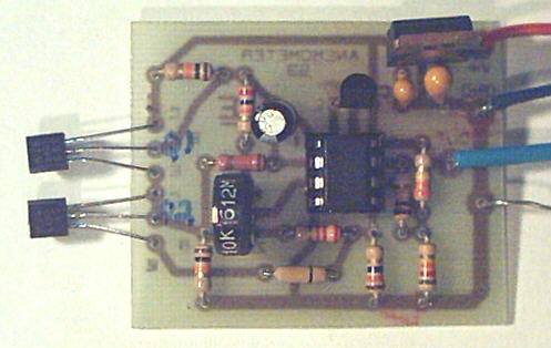
"My Assembled circuit"
Click here for the "Schematic", Redrawn by me.
All Imformation in this Article is "Copyright protected".
Chemelec
*Copyright © 2004*