I REMOVED my Origional Desulfator Project because I did Not consider it as Practical.
CONSIDER THIS: Desulfators that are Self powered by the battery they are also desulfating, are also Draining the battery, thus leading the way for More Sulfation. If you add a Battery Charger to maintain the Battery, it may help to Eliminate this possibility. But it can also interfer with the Desulfation Process.
But I find MOST PEOPLE DON'T Do this. And the IDEAL Solution is to actually have the Desulfator, Powered by a SEPERATE POWER SOURCE.
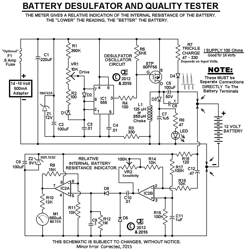
"Here is my NEW Desulfator/Tester".
This Circuit helps to Desulfate a Lead Acid battey. Besides the Pulse Spikes for Desulfation, it also gives a Small amount of a "Trickle Charge", and an Additional circuit also gives a indication of the batteries Internal Resistance.
NOTE: Some Batteries can be Improved, Some NOT. Sulfated Plates are only One of Many different battery problems. So it all depends on whats wrong with your battery?
BEFORE you attempt to Desulfate a Lead Acid Battery, Test Each Cell for Specific Gravity with a battery tester. NOTE: This Isn't possible on "SLA" Batteries or "Maintance Free" Batteries, But if the Battery won't hold a charge of 11 Volts or More, Chances are it is NOT GOOD at all.
If just "One or Two cells" are really LOW, compared to the others, You have a "BAD Battery" and attempting to Desulfate it, WON'T Help.
In a Sulfated battery (Or an Under-Charged Battery), All Cells should read Very Equal, but Low readings.
In a Really Good Battery, All cells will be EQUIL in Specific Gravity and at a charged level.
This circuit produces a Pulse Current Spike to help Desulfate a battery.
Additionally, the other part of this circuit detects this Pulsed Current Spike,
"Directly At the Battery Terminals".
This signal is than amplified and gives a reading on a Micro-Amp Meter.
And this reading will reflect on the Internal Resistance of the battery,
So the "LOWER the meter reading the better".
Sulfation Causes Higher Internal Resistance and Internal Resistance in a Battery
Reduces its ability to drive High Current.
This Circuit will NOT Work for Desulfating a Single 6 Volt Battery.
But Two 6 Volt batteries could be Connected in Series.
And using one good Battery with the Desulfated battery is Best.
In Theory, with "Unlimited Sensitivity", and with a "PERFECT Battery", the meter
reading would always read "ZERO".
However, This will NEVER HAPPEN on a Real Battery.
And in Real Life, Smaller Lead Acid or Sealed Lead Acid Batteries will have Higher
Meter Readings than Large Car Batteries.
This Desulfating Process, "May take a LONG TIME".
This Process may be anything from a "Day or Two" for just General Battery Maintance,
and up to "Several Months for a really Bad Sulfated Battery".
And the battery Should have a Reasonable Charge on it for Both the Desulfator & Tester to work.
It should be Greater than 11 Volts, Before you start this Desulfation process.
Otherwise the Tester Meter Circuit won't work properly.
NOTE:
Normally I recommend the Drive control to be set to a 50% rotation.
And than set the Vu Meter to give a 0 Db Reading.
Assuming you have a Sulfation Problem, Eventually the Reading should go Lower.
Comparing Batteries:
If you have Two Batteries of the same A/H Rating and Size and both Fully Charged,
you can set the Sensitivity control to give a specific reading.
(If using a meter obtained from me, Possibly a "0 VU" reading on the first battery.)
Than Without changing Either the "Sensitivity" or "Drive" Controls, connect this unit to the second battery
and get a Comparative Test Reading.
The Battery with the LOWER Reading, Will be the Better Battery.
As an Example:
I have Two 12 Volt 4 A/H Batteries. One is about 12 Years Old and One is Quite New.
Starting with the Old One and Setting the Drive Trimmer pot to 50% and the Sensitivity Trimmer so it reads 0 dB.
Than transferring the Leads to the Newer one, The reading is down below -10dB.
However the Old one is Just Plain OLD, and Not a Sulfation Problem.
NOTE: The Range of Adjustment for the Sensitivity Control was "Arbitrary", determined by me.
** Since I Didn't have a "NEW, EXCELLENT QUALITY, BIG Car Battery", this Range of Gain,
was just a Guess on my part, "Based on tests, using Batteries I presently have".
And so far it seem to be a Good Adjustment Range.
In My Tests, I find that the 100K pot is Basically Satisfactory.
However If you want the Greater Sensitivity, Just Increase this pot to 250K.
NOTE: On this Prototype, I just use Trimpot controls. However, you can put this board into
a suitable box and use a Convential Potentiometers For Better Ease of Adjustment.
I Definately Advise you to Put a 1 or 2 Amp, InLine Fuse between the Battery and this Circuit. (Because if either "C5" or "C6" were to Fail, this will protect the Choke and Battery)
And a 1 Amp, InLine Fuse between the Power Supply and this Circuit is also Recommended.
 Go Back to My "Projects Page"
"The Schematic"
This is the Revised Schematic.
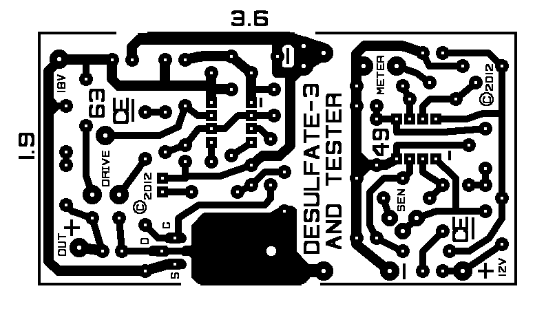
"The PCB"
Also a Revised PCB.
A "Picture Overlay".
NOTE: There have been a Few Minor Changes, since this picture was taken.
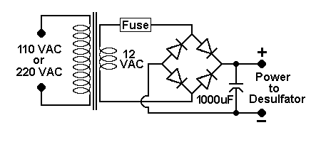
 "A Simple Power Supply for this Desulfator"
This Article is "Subject to Modifications"