Created: "Oct 22 2005"
Corrected two Part Values on Overlay Picture and Added another Picture: "Nov 16, 2017"
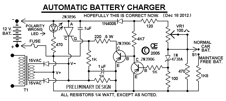
If Built and Setup Correctly, It will safely charge at 10 Amps and Automatically Regulate down to a Trickle Charge.This Charger Can't be used as a Power Supply, Without having a battery in place. The Battery MUST be Connected to get power out.
Note: This Charger Features a Reverse polarity Indicator. Instructions: Before plugging this charger into the 110 volt line (or turning it on if you use a Switch), FIRST Connect this Charger to the Battery. In doing so, No Damage will occur if the battery is accidently connected in reverse, but the Reverse Polarity LED will light up. If that LED Does light, Reconnect the battery Correctly, than apply the 110 line voltage.
Connecting the Line voltage, With a reversed battery connection, WILL Result in Damage. Especially if you don't use the fuse on the output, as shown in the schematic.
Although Not Shown in the schematic, A suitable Line fuse would also be advisable.
Some Additional Notes:
There is No Amp-Meter shown, But I would Definately recommend including one in either the positive or negative line, going to the battery.
The Transformer, Diodes and SCR, Must be caplable of handling the output current. And Don't use a 10 amp transformer. If you expect to charge battery's at 10 amps, Allow youself a Safety margin! Use a 15 Amp transformer. Also the Diodes and SCR will Definately require a Suitable, LARGE Heat Sink!
The 100 ohm trimpot on the PCB sets the Maximum Charge Voltage. To set this Correctly, attach a Fully charged battery to the output. Than using a meter to monitor the output,Set the trimpot to give an output of 14.5 volts at Very Near ZERO CURRENT.
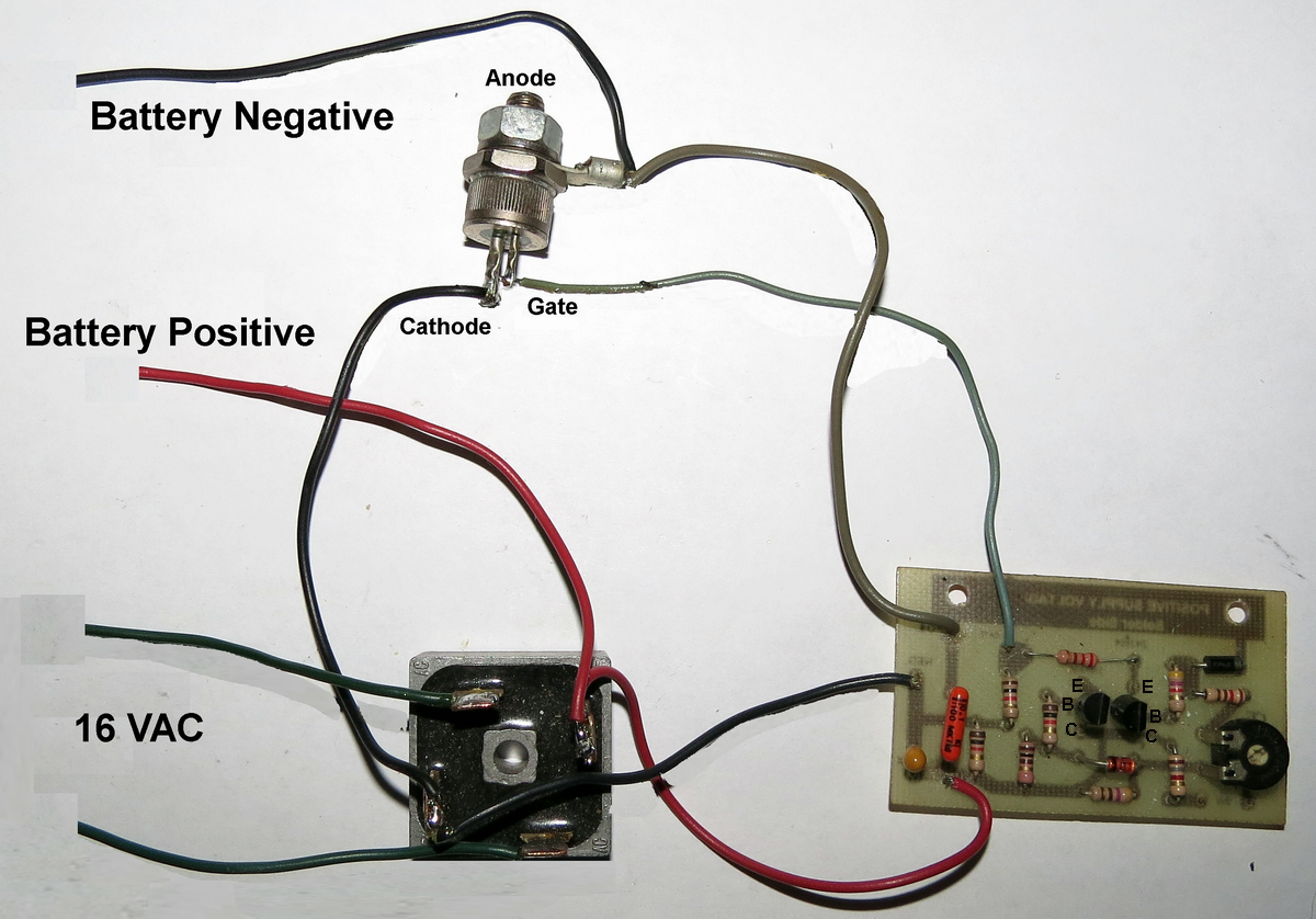
I Show a Center Tapped Transformer and two Diodes, But a Single output, 16 Volt transformer could be use with a full wave bridge rectifier.
Some manufacturers recommend Charges with a Low Output, AC Ripple content. If this concerns you, You can add a large Filter Cap across the output. However this Capacitor will NOT be Protected by a reversed battery, unless it is connect before the fuse in that line.
"Back to My Projects Page"
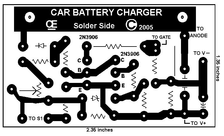
"This PCB is Correct, Except the "C" & "E" on the Transistors are Revered." I can supply a PCB, if its needed by anyone.
"Picture Overlay, Tested and Correct"
"Total CONNECTIONS Picture, I Believe I did this Correct,"
All Imformation in this Article is "Copyright protected" and "All Rights Reserved".

 Chemelec  *Copyright © 2005 & 2017*