The Probes:
For Conductive Liquids: These may simply consist of Two Parallel Metal Plates. If the Container is Metal, that could act as one of the plates. NOTE: A Suitable metal is required for Acid or Alkaline Solutions.
Although this circuit is mainly designed for Conductive Liquids and just two probes, it may be used with any variable resistance device.
Some Other sensors that can be used:
a) Light Dependant Resistors b) Photo Transistor (possibly for Soil or Oil) c) Thermistors (Possibly used for temperature changes)
The Emitter of Q1 is the circuits "Voltage Reference" (Aproximately 4.75 volts) and the circuit switches when the Base of Q4 gets a signal of about 0.4 Volts.
This circuit is quite simple, Definately Sensitive and works well. It is protected from Transient Spikes, so it is safe to use in a car.
More Explainations:
This circuit is good for detecting the presence, absence, or level of water, or other polar liquids.
When in use, an AC signal is passed through the liquid between the two probes. This detector than compares the fluids resistance to the internal resistance of RX.
"Operating Frequency", Depending on Tolerances, this frequency is typically between 4 to 5Khz.
"CX", is Mainly used with Inductive Loads. On the Schematic it shows a Visual LED and a Pizo Speaker, But these could be replaced with a Relay. Note: Do NOT Use this Capacitor if using the Pizo Device or a Speaker. It Will Stop 4 to 5 Khz Frequency from coming through.
"RX" Reference is typically 15K and it is coupled to a 0.047 uF Cap. However it may be in a range from 1K to 100K. The .047 capacitor is provided so there is no Net DC Voltage on the Probes. The use of an AC Signal also prevents any Plating effects from occuring on the probes.
As Shown on the Schematic, This 0.047 capacitor can be Bypassed, allowing for a DC Flow. Obviously, This is Not Advisable for Flamable Liquids.
A Formula for you.
It is Possible to calculate the resistance of any aqueous solution of an electrolyte for different concentrations, Provided the dimensions of the electrodes and their spacing is known.
The Resistance of a "Simple Parallel Plate Probe" is given by:
1000 d OHMS R = ---- * ------ c.p A
A = AREA OF PLATES
d = SEPERATION OF PLATES (cm2)
c = CONCENTRATION (gm. mol. equivalant/liter
p = EQUIVALANT CONDUCTANCE (Ohms -1 cm2 equiv. -1)
Note: An Equivalant is the number of moles of a substance that gives one mole of positive charge and one mole of negative charge.
For Example:
One mole of NaCl gives Na+ +Cl-, so the equivalant is 1 One mole of CaCl2 gives Ca++ +2Cl-, so the equivalant is 1/2.
Usually the probe dimensions are not measured physically, but the ratio d/A is determined by measuring the resistance of a cell of known concentration c and equivalant conductance of 1.
** The above is a Quote from a "National Semiconductor Linear Data Book" of the year 1988.
So PLEASE, DON'T ASK ME Any Questions on this!
Maybe more Info Later:
Etched and Drilled PCB'S are available.
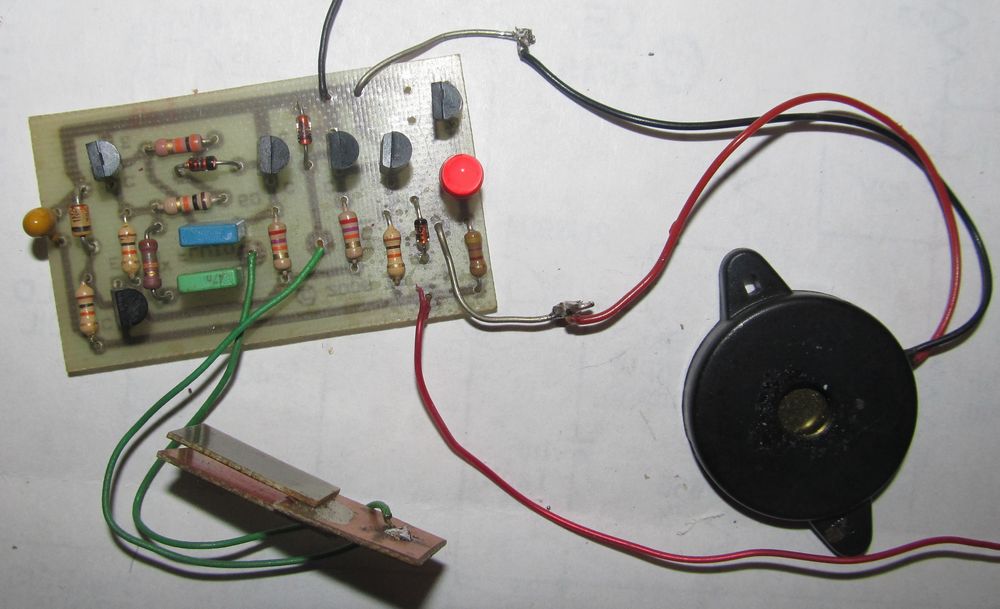
In his Picture I have a Very Simple Probe, just made out of PCB.
With Too Much area on the probe, the circuit will trigger because of capacitance.
The Sensitivity can be lowered by increasing "RX".
