Latest Update:"June 15, 2008".
This circuit board "Is Available".
I can also supply a kit of parts, But Excluding Heatsinks.
This circuit is designed on a basis of Simular Generators that are being offered in the market place and it Should be Just as Effective. Also this unit can Probably be Built MUCH CHEAPER.
The Only Purpose of this circuit is to provide a "Variable Frequency", with a "Variable
Pulse Width". In theory and in test results I have seen, this provides a more versitle
method to generate Hydrogen than using just a DC voltage in Electrolysis.
This device is especially Useful to control the Current Draw through the cell.
And this Device is Also helpful in getting a Learning Experience and just to have fun with.
"This Circuit has been Tested and functions correctly, as a Pulse Generator for this purpose".
Any Substantial Quantities of Hydrogen Gas.
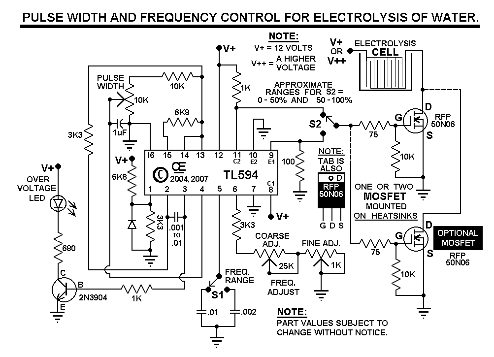
 "REVISED SCHEMATIC", Mar 2007.
This Circuit Also Includes a Fine Frequency Adjust.
"Parts Overlay for PCB for External Mosfets and Heat Sink."
All pots shown are Trimpots.
However Regular Pots and Toggle Switches could be used instead.
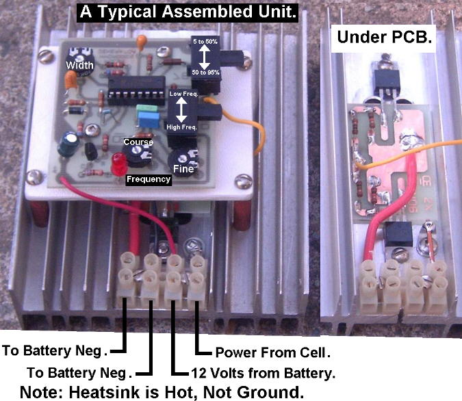
"Revised PCB for External Paralleled Mosfets."
"A Typical Heat Sink with Paralleled Mosfets."
Now, More About My Simple Hydrogen Generator this Circuit.
1) With a .01 Capacitor and a 50K pot, the Measured frequency range is about 1,300 to 17,000 Hz.
Using a .01 cap and a 25K pot, the Measured frequency range is about 2,250 to 17,000 Hz. Using a .002 Cap and a 25K pot, the Measured Frequency Range is about 10,000 to 71,000Hz. This gives Two Good Overlaping ranges with a Toggle Switch.
Remember Tollerance variations can change these ranges and Many Other Potentiometer and Capacitor Variations are Possible for different frequency ranges.
2) This Circuit has an LED Indicator for OVER-VOLTAGE and it Shuts down the circuit at about 15 Volts. This Protects the IC and the Gates of the Mosfets.
3) This Shut Down is Just for the PCB, it is Not Affected by the Supply Voltage to the Probes used for Electrolysis. That Voltage Can Be Hundreds of Volts, Limited only by the MosFets Used. But Once shut down, the Mosfet turns off until the supply voltage to the PCB falls back below the 15 volts
4) In the Circuit with the On-Board Heatsinks, One Mosfet Drives a 5 to 50% Duty Cycle. The other is inverted with a Transistor and Drives a 50 to 95% Duty Cycle. You can use Both Seperately, but also Simutanously, or incorporate a SPDT Switch on the PCB to switch in Either Range for a single, continuously variable output.
5) In the Circuit with the External Heatsink, A Switch changes from the 5 to 50% or the 50 to 95% Duty Cycle Range.
A Few words about Generator Construction:
1) The Generator cell must have reasonable surface area on the Plates to generate a reasonable amount of Hydrogen/Oxygen. And a Typical construction would use Stainless Steel for the Electrodes to prevent them from being Quickly eaten away.
2) While a Generator can Generate a reasonable amount of Pressure, I Believe it is more important to release Pressure and generate a Volume of gas. In My Opinion, Keeping hydrogen under pressure in the generator, compresses the bubbles, holding them to the electrodes longer, hindering further production.
DANGER: Hydrogen IS VERY EXPLOSIVE.
So Be Very Careful with How you do all this stuff.