Created: "June 11 2008" Revised: "August 27, 2008"
"Go Back to My HOME Page"
Unlike conventional PWM Circuits, This circuit also has a special "Current Limit Control". "If your H-Cell gets hotter and tries to draw more current, This circuit won't let it". NOTE: This Circuit is Not my Design, it is from: "http://www.alt-nrg.org" However I have Modified it slightly, designed a Circuit board for it and Tested it. "This article is written and posted with permission of the owner of that site". This circuit has 3 controls: 1) With the parts as Shown, (Except VR2, I use a 25K pot) the Frequency is from about 500hz to about 3500hz. Changing the Value of C1 will somewhat change this range. Tested Results on the Schematic. 2) The Duty Cycle is adjustable, Basically from 0 to 100%. 3) The Current Limit is adjustable over a Substantial Range with R12 as Shown. R12 is made with a 4.5" piece of Stranded Heater cord, with one end soldered together to form a U Shape. Or a Single 9" length of 16 AWG Automotive Copper Wire. See Additional R12 Info on the Schematic. Increasing R12's resistance will allow for a Lower Current range, and Visa-Versa. Sorry I Don't have a Power supply Big Enough to actually test these Limits.
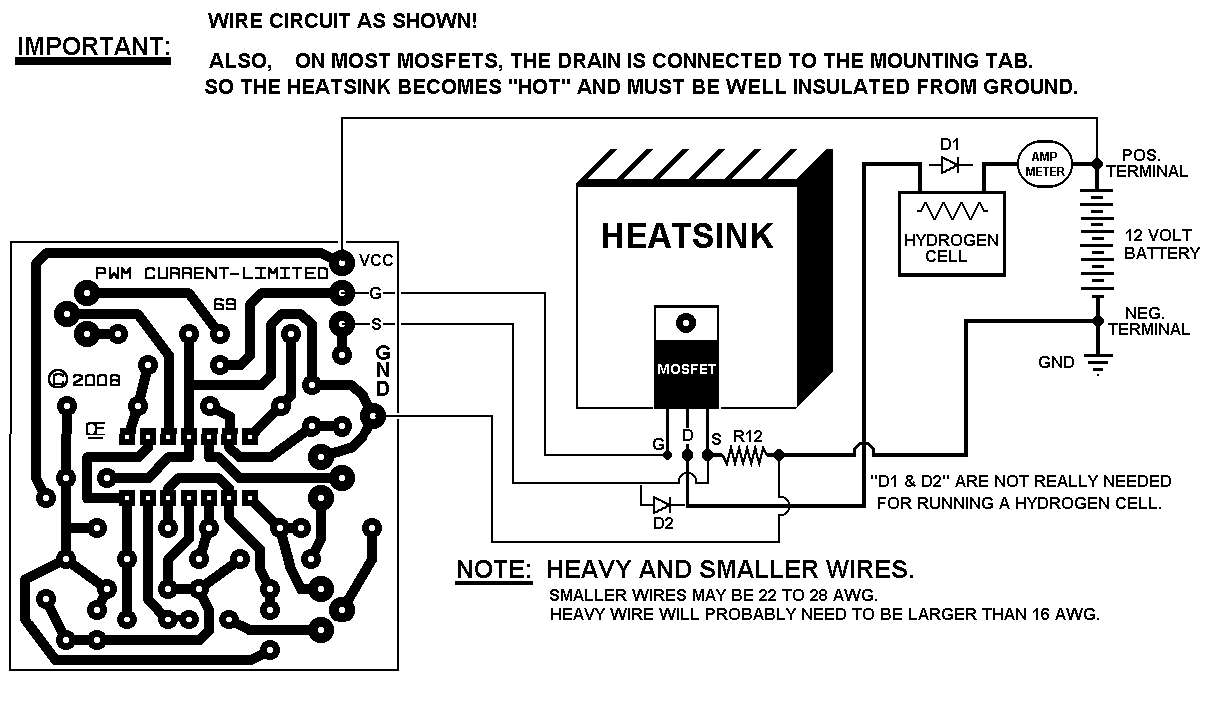
Q1 Mosfet "MUST be Mounted on a Suitable LARGE Heatsink". ** If it gets too Hot to hold with your hand, You probably need a Better Heatsink.NOTE: When this circuit goes into Current Limit Mode, "Q1" Can get EXTREMELY HOT, as it actually becomes a Variable Resistance Device.
Setup Procedure.
1) For proper adjustment of this device you need an Amp-meter in series with your cell.
2) Next, set the frequency Where ever you want. In my opinion, the frequency makes very little difference.
3) Set the Current Limit control, Full Off. (Wiper of pot is to the 100K resistor.)
4) Set the PWM to the Current of your choice with the Cell Cold.
5) Now adjust the Current Limit Control, so that the Current just starts to show a DECREASE on your Amp-meter.
6) Now as the cell gets hot, this circuit should maintain a Fairly constant current.
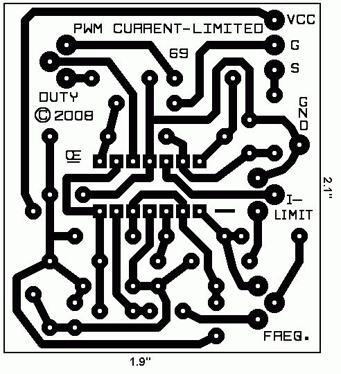
The Schematic. The PCB. I Created this small circuit board for this project. It will be available if needed.
Experiment, Have Fun And Enjoy.
All Imformation in this Article is "Copyright protected".
Chemelec
*Copyright © 2008*