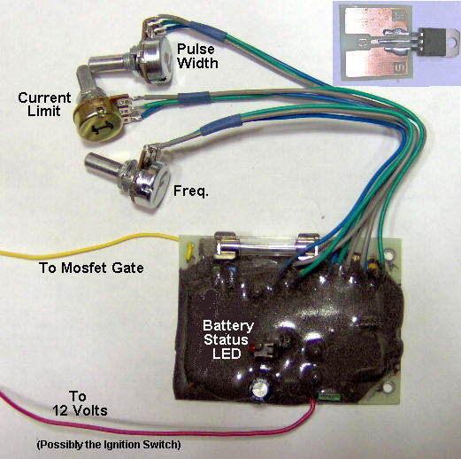
** My "Ultimate PWM-1" has a Pulse Width, Frequency and Current Control.
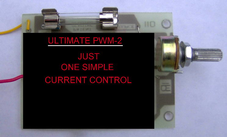
Like ALL PWM Circuit, "It will NOT increase Gas Production", "PWM ONLY Helps Control the Flow of Current".** My "Ultimate PWM-2" doesn't have a Pulse width or Frequency Control. (The Frequency is Preset at about 21khz and Pulse Width is auto-controlled.) So it ONLY has a "Current Control", for Much Simpler Operation. And in My Opinion, this "Ultimate PWM-2" works just as Effectively as the "Ultimate PWM-1", and with less hastle.
EXTREMELY IMPORTANT, for Both Units: 1) The 12 Volt Positive Wire from your Cell, MUST connect Directly to the Positive Battery Terminal. 2) The small 12 volt wire from the circuit board can either connect Directly the Battery Terminal, or to your Ignition Switch. 3) DO NOT Join these two 12 volt wires together, to than connect to the battery. NOTE: Failure to do this correctly may allow high current spikes to damage this PWM device and or other sensitive devices in your car. (Such as your cars Stereo System or its Computer.)
This Article was Origionally Created: "SEPT 23 2008". This Latest Article Update is: April 11, 2009.
All info here-in is Copyright and **Patent is Pending.**
Unlike conventional PWM Circuits,
My "Ultimate PWM Circuits" are "Very Unique in How it performs the Current Limit".
"When your H-Cell gets hotter and tries to draw more current,
When Adjusted Properly, These Digital circuits won't let it".
And they do this Current Control, "Very Efficiently".
SOME Other Unique Features:
1) Both circuits have Automatic Shutdown for:
Under Voltages and Over Voltages.
If the LED light comes on, it means your Battery and/or the Alternator
is NOT Working Correctly. (Normal range is approximately 11 to 15.5 Volts.)
2) On the Ultimate PWM-1, the Frequency is Adjustable over a pre-determined range.
This Frequency is about 5khz in a Counter Clockwise Position
to about 22 khz when turned fully Clockwise.
I can change this Frequency range substantially.
However, I see no good reason to doing this, as the Frequency
has very little, IF ANY Effect in hydrogen production.
Besides, As the Current Chages, So does the Pulse Width and Frequency.
So this unit is Not Really Practial and it
3) On the Ultimate PWM-2, the Duty Cycle is adjustable, Basically from about 0 to 100%.
4) On Both unit, the Current Limit is adjustable over a Substantial Range.
(Basically from near Zero current to about 35 amps maximum.)
IF your load is a DEAD SHORT for any reason, "you will distroy the Mosfet".
This is because the "Instantaneous current" is MUCH Higher than the Average Current.
However, in my tests, it did not damage the circuit board parts.
5) On Both units, The circuit is Fused at 35 amps for added protection.
In a Vehicle, 35 amps is More than your Alternator can deliver on a
Continuous basis, So there is no reasons to go higher than that.
DO NOT Replace this fuse with Any other Brand or Size,
as this may result in Permanent Damage to the circuit,
And WILL Result in Improper Operation.
I can supply an Additional Fuse, "If requested to do so".
NOTE: Typically a 100 Amp Alternator
can only deliver about 50 Amps of "Actual Continuous Current.",
However, out of that 50 amps, it must run the motor, headlights,
heater and other accessories.
So probably about 20 amps is All you should use for Hydrogen Generation.
But with this circuit, your wire gauge going Directly to the Negative of
the battery should be a "Minimum of 12 AWG", and as short as possible.
Will Not be Available anymore.
Typically if Operating at 20 to 25 Amps, the Wire from the battery to the cell, as well as the wire between the Mosfet and the cell, can be a 14 or 12 AWG and Length of these wires isn't too much of a problem. MAKE SURE ALL YOUR WIRES are "Clear of any Hot Parts or Moving Parts, that may Melt or Damage its Insulation", Thus Causing a Short circuit. And an Additional 30 Amp Fuse in the battery lead to your cell, Would be a GOOD added Protection against this happening. IT'S BETTER TO BE SAFE, THAN BE SORRY.
Just for Information Purposes:
A 10 AWG Copper wire has .001014 Ohms per foot. At 20 Amps, this .001014 Ohms = .02028 volts drop per foot. A single 10 AWG wire in open air, with Ambient Temp at 135oF and a current of 55 amps, wire temp may reach 212oF.
A 12 AWG Copper wire has .001619 Ohms per foot. At 20 Amps, this .001619 Ohms = .03238 volts drop per foot. A single 12 AWG wire in open air, with Ambient Temp at 135oF. and a current of 41 amps, wire temp may reach 212oF.
A 14 AWG Copper wire has .002575 Ohms per foot. At 20 Amps, this .002575 Ohms = .0515 volts drop per foot. A single 14 AWG wire in open air, with Ambient Temp at 135oF. and a current of 32 amps, wire temp may reach 212oF.
A 16 AWG Copper wire has .004094 Ohms per foot. At 20 Amps, this .004094 Ohms = .08188 volts drop per foot. A single 16 AWG wire in open air, with Ambient Temp at 135oF. and a current of 22 amps, wire temp may reach 212o.
Will Not be Available anymore.
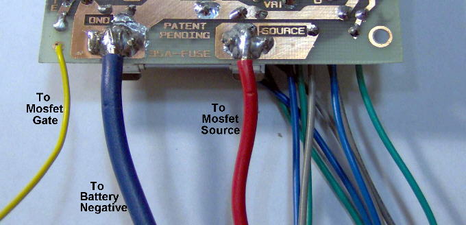
The Solder and Wire Connections.
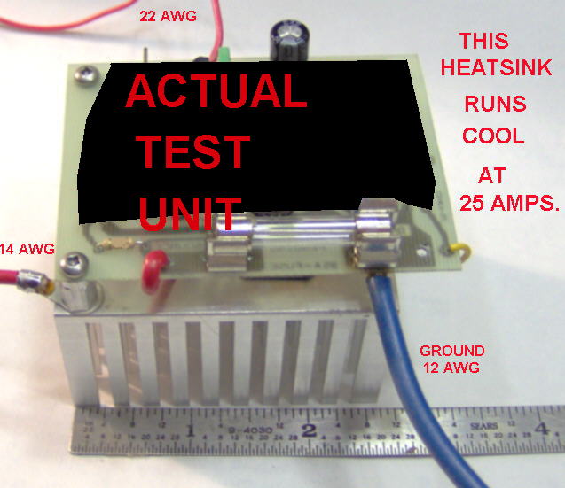
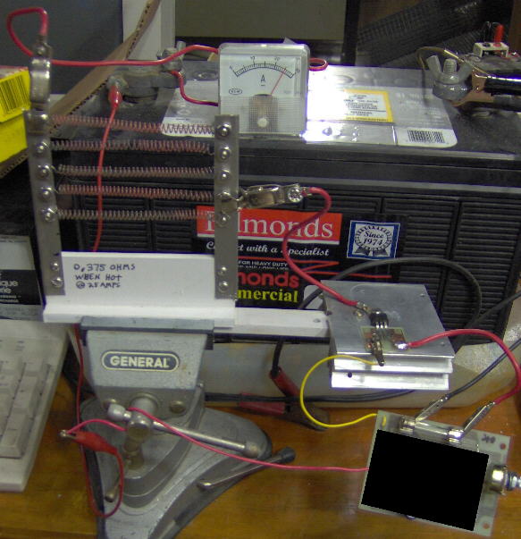 Here is my test setup in operation.
I Test All Completed units on this to ensure reliability.
Ambient temperature here is typically 22 Degree Celsus.
NOTE: It will Probably be MUCH HOTTER In your Car,
so make sure your Heat Sink has "GOOD VENTILATION".
The Nichrome Load element, shown here is a 0.375 ohm Nichrome Element.
And here the current limit control is set for 25 amps.
Here is my test setup in operation.
I Test All Completed units on this to ensure reliability.
Ambient temperature here is typically 22 Degree Celsus.
NOTE: It will Probably be MUCH HOTTER In your Car,
so make sure your Heat Sink has "GOOD VENTILATION".
The Nichrome Load element, shown here is a 0.375 ohm Nichrome Element.
And here the current limit control is set for 25 amps.
 Here is the PCB and Mosfet Mounted on a Suitable Heatink.
This is the ENTIRE CIRCUIT for real operation up to 35 amps.
IMPORTANT: If you intend to Purchase this Device, Be Aware:
1) A Suitable Amp-Meter Is Essential for Setup, And it is Strongly Recommended it to Always be In Circuit. This will allow you to Constantly Monitor current, in case of any Failure.
2) You will need to supply the Heavy Gauge wires, as required. And a Suitable Soldering Iron is Required to solder these Heavy Gauge wires to the PCB. The Typical 20 or 30 Watt soldering pencil Won't Work for this. ** A Weller 120 or 240 Watt Soldering Gun would be More Appropriate. And GOOD SOLDERING SKILLS ARE ESSENTIAL.
3) You Must get a "Suitable Heatsink" and Properly mount the Mosfet on it. ** Remember "This heatsink is Electrically HOT", so It MUST BE ELECTRICALLY ISOLATED from the Vehicle Ground. Also "Your Heatsink MUST Be in FREE AIR to allow for Proper Cooling".
4) Use of this Ultimate PWM Device and/or any Hydrogen Cells, May be Illegal in any Vehicle where you live.
5) This device will be supplied with 3 convention potentiometers for control of it. You will need to mount them on a suitable panal. 6) Only the PCB's Small RED 12 volt supply wire and the Mosfet's Gate will be soldered on the PCB. This Small RED 12 volt power supply wire can be Extended in length and wired to your Ignition Switch. Then When the Ignition Switch is OFF, this circuit shuts down the Mosfet.
7) Since I have No Control on How you install or operate this device: I Do Not accept Any Liability from its use or any resulting damage. I Also accept No liability for any Errors or Omissions that may be in this article.
8) Your Letter to me when ordering this device, "Should specifically State":
"I have Read and Understand this Ultimate PWM article Entirely, and I accept All Liability hence-forth". DATED AND SIGNED by you. But Reguardless of you sending this statement, I will not be responsible for your actions.
A Typical Adjustment Procedure for the "Ultimate PWM-2":
1) Before Applying Power set the control, Fully "Counter Clockwise". (This is Basically Zero Current.)
2) Than, Watching your Amp-Meter, Set the Current as Desired.
Assuming a Constant Battery Voltage, The Current will remain Quite Constant, to what you set it for.
However, I will "NOT Disclose the schematics". They will be Pre-Assembled and Potted in BLACK Epoxy.
Cost Prices and Shipping Cost is now Available on Request.