1) Can be used with a wide range of supply voltages by using appropriate transformers.
2) Can be used to deliver a wide range of output voltages by using appropriate turns ratio.
3) Output Frequency is Adjustable and Stable.
4) A Standard Step Down transformer (Reverse connected) can be used with Fair Results for Lower Wattages.
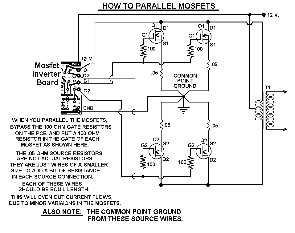
5) With the addition of "Parallel Output Fets" and a Large Transformer, Power can be GREATLY Increased.
NOTE: There ARE Limitations!
I have had numerous requests for an Inverter for 1000 watts and Even MORE.
Sorry I Don't feel this is Practical.
At 1000 Watts and operating from a 12 Volt Source, the Input Current will be close to 100 AMPS.
That would Require a HUGE Size of a Primary Wire. SORRY But There ARE Limitations!
I Definately wouldn't want to even Try to wind that.
Created "Feb 3, 2004"
Revised "October 24, 2018"
This circuit will provide a very stable "Square Wave" Output Voltage.
Frequency of operation is determined by a pot and is normally set to 50 or 60 Hz, Depends on where you live.
SOME "off the shelf" transformers can be used, but with Poor Results.
Or you can Custom wind your own FOR BEST RESULTS.
Additional MosFets can be paralleled for higher power.
It is recommended to Have a "Fuse" in the Power Line and to always have a "Load connected", while power is being applied.
The Fuse should be rated at 32 volts and should be aproximately 10 Amps per 100 watts of output.
The Power leads must be heavy enough wire to handle this High Current Draw!
Appropriate Heat Sinks Must be used on the RFP50N06 Fets. These Fets are rated at 50 Amps and 60 Volts.
** Other types of Mosfets can be substituted if you wish.
The LT1013 offers better drive that the LM358, but its your choice.
The Power transformer must be capable of handling the chosen wattage output.
Also, Appropriate Heat Sinks are Necessary on the Mos-Fets.
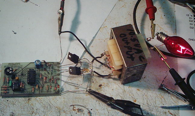
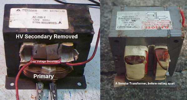
Using a rebuilt Microwave transformer as shown below, it should handle about 500 watts Maximum.
It requires about 18 turn Center-Tapped on the primary, if using a 12 volt Battery.
Since using a 12 Volt Source, Basically this transformer gets wound with a 9 Volt Primary, Due to conversion from DC to AC.
To handle 500 watts would require using a 5 AWG wire. Pretty Heavy Stuff, but so is the current draw at that power.
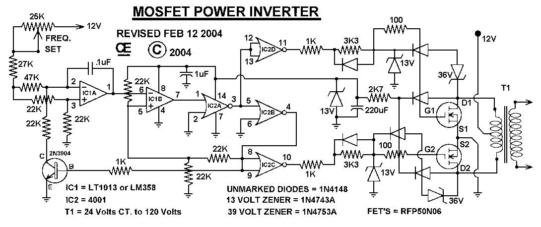
Simplified Operation is: IC1A & IC1B, Along with IC2A & IC2B and the Transistor form a
Voltage controlled Oscillator of which the frequency is adjusted with the 25K ohm pot.
IC2C & IC2D are buffers, driving the Mos-Fets, out of phase of each other.
The 13 volt Zeners stabalize supply voltages and limit signals, while the 36 volt Zeners
limit spikes from the transformer.
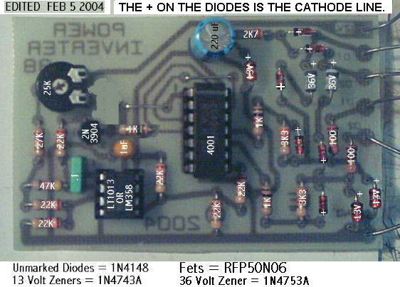
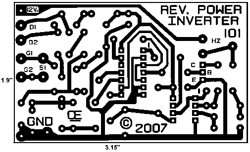
The PCB is available.
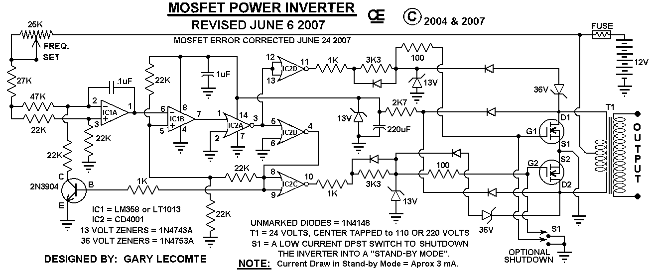
 Revised Schematic with Standy Power Switch
