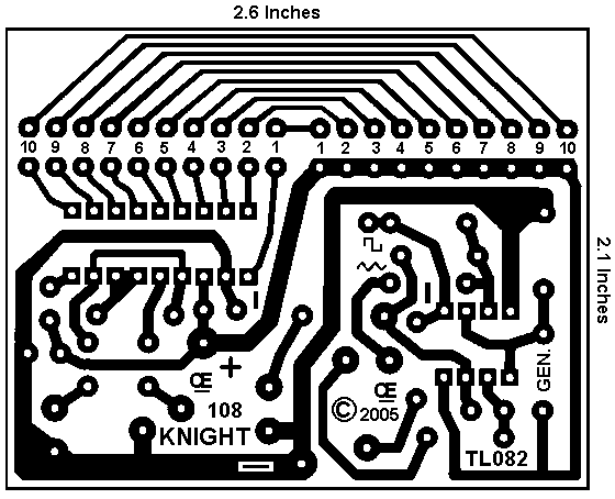
New Knight Rider Board, This Third and Best Circuit.
Both the Circuit Schematic and the Circuit Board are Below
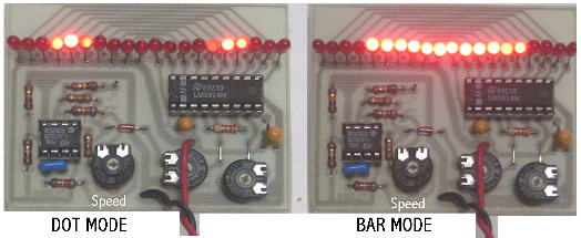
These circuits will give provide a Good Effect, duplicating the Knight Rider Lights, Plus more.
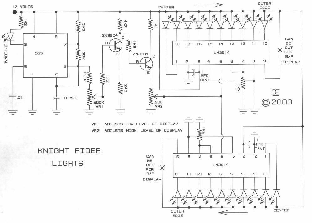
In the First Circuit By Changing the Values of the resistors on pins 6 and 7, And/Or the Capacitor on pin 2 of the 555. you can change Frequency.
I suggest you maintain an Aproximate 50% duty cycle. This will give an Even Rise and Fall.
But reducing down to 25% can give a reasonable effect also!
In the Second Circuit In the Second Circuit, the range of Frequency Adjustment should be Quite Sufficient as presented. But the .47 cap can be changed in Value for other frequencies.
This Circuit is Better than my First Circuit above, as the waveform is more symetrical and the Drive to the LM3914 is a more stable voltage with more current available.
Changes to the Ratio of the 470K to the 1M Resistor can affect both the Frequency Range as will as the Waveform Symetry. This could create a Sharp Rise and a Slow Decay, or Visa Versa. Resulting in Different Visual Effects.
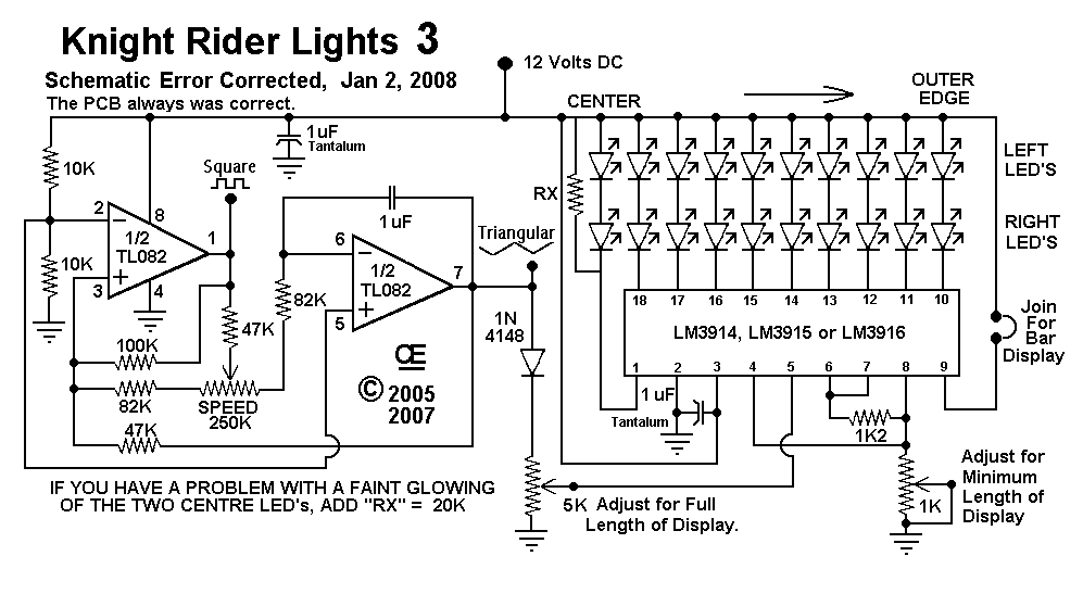
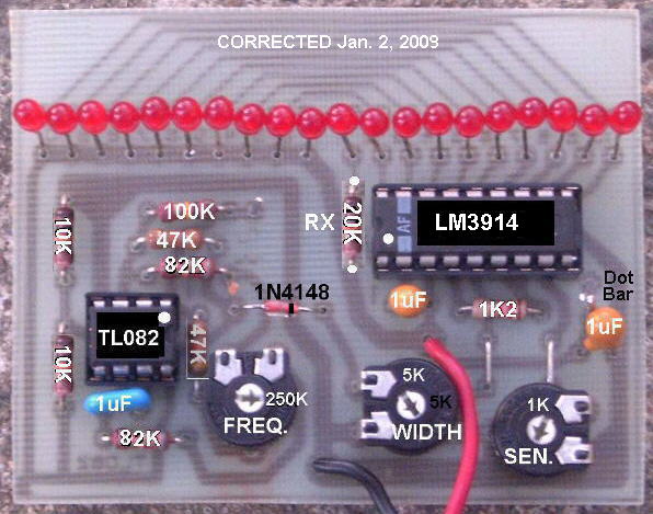
In the Third, Newest Circuit, The Simplest Circuit and Best Yet
The TL082 (Or a TL072 also is OK) Creates an Adjustable Sawtooth Generator. (It also has a Square wave Output, but it isn't used here.)
The Left and Right LED's are Connected in Series and if this circuit is used on a 12 volt system, and if a person wanted to they could connect 2 LED's for each LED Shown. Additionally I show the LED's Mounted on the Circuit Board, But they can be wired OFF Board if So Desired.
1) There is a 1K Pot that adjust the Voltage input to the LM3914. 2) There is a 5K pot that adjust the Output voltage of the Sawtooth Oscillator. 3) There is a 250K Pot to set the Frequency as Desired. 4) Additionally there is a Connection point between Pin 9 of the LM3914. Joining these together to creates a Bar Display. 5) Substituting an LM3915 or an LM3916 will create a Non-Linear Effect in the Lights.
Return to my "HOME Page"
Another Schematic, Second Circuit.
All Information in this Article is "Copyright protected".
Chemelec
*Copyright © 2003, 2005, 2008*