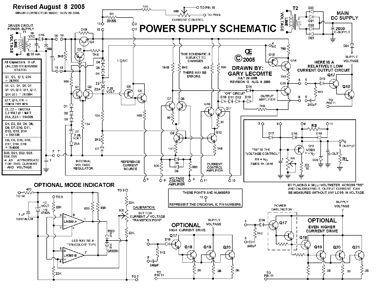
Note: This is a Heavy Duty, "Lab Grade Supply" and can handle Hundreds of Volts and/or Very Large Currents. It is Based on the MC1466L Integrated Circuit, which has now been Discontinued for Many Years. This Transistor Equivalant Circuit can also be used as a Direct Replacement for the MC1466L IC.
The Info Presented Here Is Greater than the Origional IC. I have added Most of the Extra Protection circuits as well as a E/I Mode Feature. I Believe this documentation is Correct, But I will not assume any lialibility for Errors or Omissions. Also Since this is Line Operated, Take Special care in this wiring to prevent Possible Electric Shock.
Although this Power supply LOOKS Complicated, It is Not that Difficult or Expensive to build.
The Transistors, Zeners and Diodes are Very Common types. However, As with Any Power Supply, The "Main Power Transformer", "T2" in this Circuit, may be costly. If Extreme Accuracy is not Critical, 1% Resistors can be replaced with the Nearest 5% Values.
I Designed the board for a "Hammond" Transformer for "T1", because it is a good product made here in Canada and readily Available to me. But you could substitue other types with the Approximate same voltage.
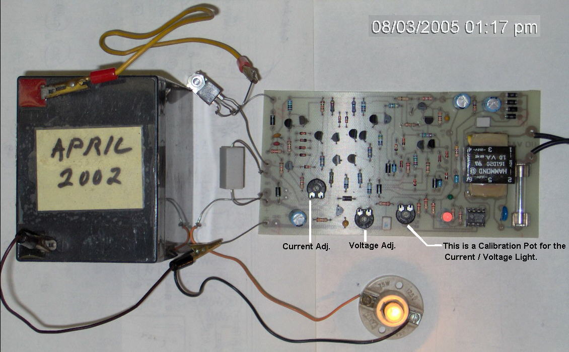
I Built a Dual, Isolated Version of this for my own use: "Seperate Power Transformers for Each one" They are Each rated at 35 Volts and 8 Amps, Continuous Output. I can Parallel them for 16 Amps. Or Series them for 70 Volts Or use them in series connection as a Plus and Minus Supply, with center as ground.
I have also designed an Upgraded Version of this circuit with additional parts to display if it is operating in Voltage Mode or Current Mode. I have posted this as the Final Circuit and the PCB for it. You can Either Add these few additional parts, Or leave them off. The choice is yours. The Output Voltage and Current requires that Q17 and Q18 be capable of Handling both the Voltage and Current. These create a Darlington pair and can be Multiple, Parallel Transistors. The Main Requirement for High Output Current is: First, having enough "Gain" in the Darlington Pair Second, Parallel Transistors Capable of both the Voltage and Current Requirements. More info to come about this later. T1 Supplies power to the Control Circuitry and is Typically just a Small 50 mA, 18 VAC Transformer. T1 is an Isolated Supply from the Actual Power Supply Transformer. T2 is the Actual Supply Transformer and Must be capable of whatever Voltage and Current you require. Because of Supply Filtering it should be Over-Rated in Current by at least 25%. This is True for All Analogue Power Supplies, if you want the rated output. The Filter Caps on the Supply for T2 should be at least 100 uF per Amp. So for a 10 Amp Supply, it requires a "Minimum" 1000 uf Cap. But I would Recommend Considerably More Capacitance. Resistor "RS" is set to Drop 0.25 Volts at the Rated Amperage you have chosen. If this resistor is well rated and doesn't change resistance with the Heat, resulting from Higher Currents, A Milli-Voltmeter placed in Parallel with it can be Acurately Calibrated for the Output Current. I used a 3 1/2 Digit, 199mv Digital Panal Meter for this purpose. (Set for 0 to 9.99 Amps)
It Works Very Well and there is No Output Voltage Drop that always occurs when you place an Amp-Meter in series with any supply. In this case, This voltage drop is corrected within the circuit. However there will be Some Voltage Drop in your Probe Wires.
I also used another 3 1/2 Digit, 199mv Digital Panal Meter for the Voltmeter. (Set for 0 to 99.9 Volts) Additionally I use 10 Turn Pots for Both the Voltage and Current. This Gives a Very Accurate adjustment of both. After Running this Circuit for over 20 years, The only failure I had was a set of Output Transistors, Caused by a Very High Voltage Spike from a circuit I was Driving. Actually the Only time I Turn OFF my power supply is when I am away on Holidays. To Reduce Heat Sink Size, you can Add a Fan, Like I have done on Mine. I also put a Thermal Switch on the Heatsink so the fan Only runs when necessary.
Design Considerations:
"RS" is Set to Drop 0.25 Volts at Full Current Out. For 5 amps Maximum Current Out, RS would be .25 Divided by 5 = 0.05 Ohms For 10 Amps Maximum Current Out, RS would be .25 Divided by 5 = 0.025 Ohms
"RX is a Value Equivalant to 1000 Ohms Per Volt. As an Example, a 25 Volt Supply would use a 25 K Pot.
The Collector Resistor on Q16 is set for RX Divided by 10. So on the Above Example, this resistor would be 2K5.
"C-Out" is Typically set at 100 uF Per Ampere Out. So for 5 amps Maximum out, C-Out would be 500 uF.
"C-Supply" Should have a Reasonable Capacitance for the Maximum Supply Current. I Would Recommend a Minimum of 1000 uF per Ampere.
For Optimum Regulation, Select the output Transistors such that:
Current Out, at Pin 5 Should not Exceed 0.5 mA. DC. (500 uA)
Therefore:
I Maximum ----------- = Less Than 0.5 mA. DC. (.0005 amps or 500 uA) B1 B2
Where Imax = Maximum Short Circuit Current mA. DC.
Beta = HFE = Is the ratio of Collector Current to Base Current For Example: If a 1 mA base Current cause the Collector Current to go to 100 mA, that the Beta is 100.
Ic Beta = ----- Ib
B1 = Minimum Beta of Q17 B2 = Minimum Beta of Q18
Although Pin 5 Will Source about 1.5 mA. DC, Currents Greater than 500 uA will Result in Degration of the Regulation.
Examples:
A 2N3904 has a Minimum Beta of about 100 A 2N3055 has a Beta of about 20
100 X 20 X .5 mA (.0005 amps) = 1 Amp
In My Unit, I Used an MJE1100 with a Beta of 750 and 2N6328 with a Beta of about 35.
750 X 35 X .5 mA (.0005 amps) = 13 Amps I also Paralleled 2 of the 2N6328's to give better Heat dissipation.
"Back to My HOME Page"
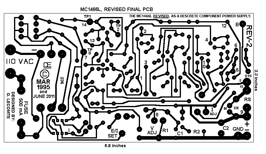
The Schematic This is Updated to have the Current/Voltage Indicator. Hopefully I have All Errors Corrected.
For this demonstration, I am just using a Battery as the Supply's Actual Power Source. And just a Single TIP121 Darlington Transistor for the Output.
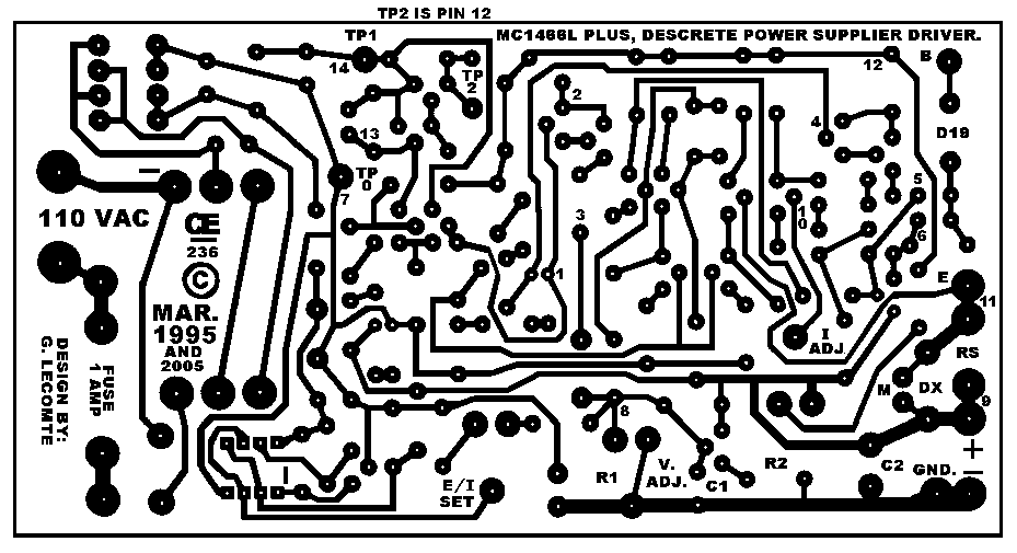
The "M" on the PCB is for a Milli-Voltmeter, Calibrated to Measure Current.
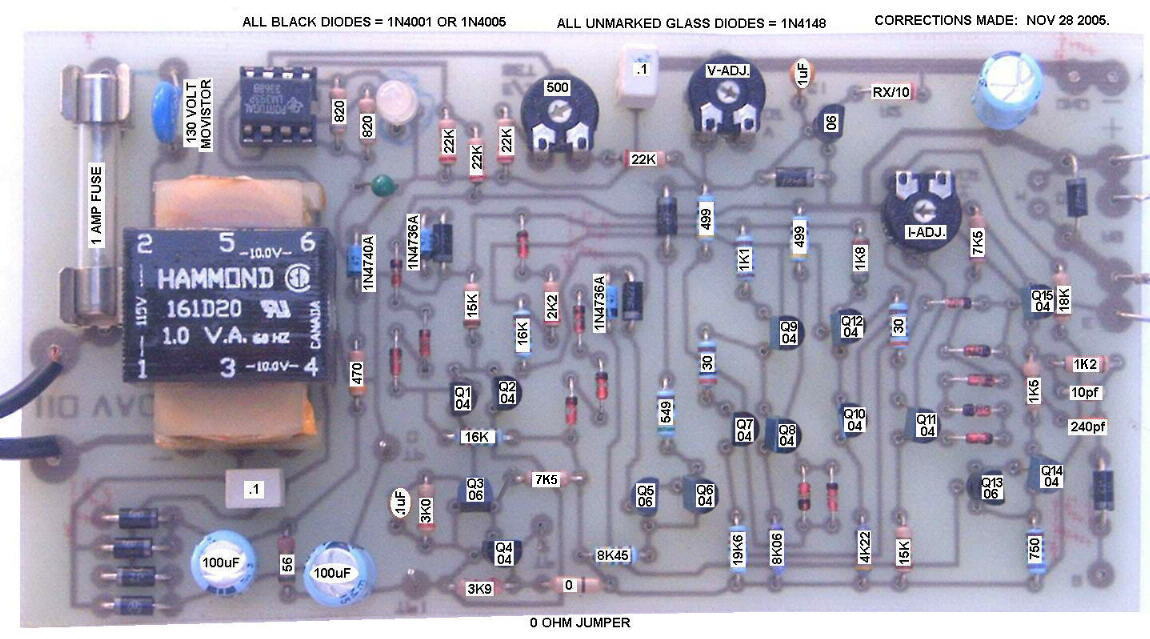
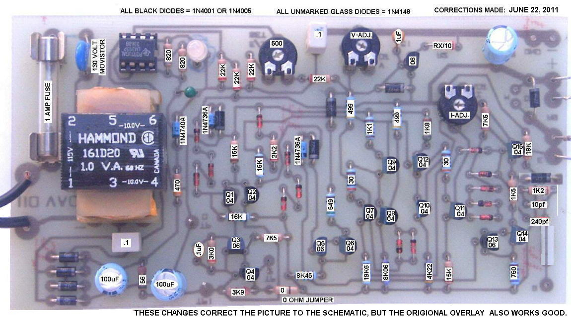
After all these years, it was brought to my attention of another PCB ERROR. Although the Above Board Does work very well, I decided to include this Corrected one.
Picture of this revised PCB
"I Assume No Liability from the Construction or Use of this circuit"
Build and Use it at your own risk!
All Imformation in this Article is "Copyright protected".
Chemelec
*Copyright © 2005 & 2011*