In the unit I built, I used IC sockets for all the 8 pin dip IC's. I would suggest you do also!
I had considered using 4000 series IC's in the timing circuits but decided against it. Too many In-experienced hobbiests have problems with C-Mos. C-Mos would result in a slightly lower total current, but most of the current draw is from the coil, not the IC's. I also find that 555's are Easier to Control for Frequency, Duty Cycle and Pulse Widths.
I supply good quality parts.
Carefully assembly the PCB and AVOID Touching the Copper traces with your Fingers. Touching the Copper causes OXIDATION and Results in Cold Solder Joints. Good Soldering is a "MUST DO".
Assembly
I Recommend Soldering on the Jumper wires First. Than Resistors, Followed by IC Sockets. I recommend Diodes be Placed about 1/4 inch Above the PCB. Than add the Caps, Regulators, Fet, Transistor and Mosfets. Than, Recheck board for any shorts! Lastly, WASH the Boasrd to Remove the Solder flux and DRY IT.
1) Only insert IC2 into it's socket, leave out the rest of the 8 pin IC's for now. As A Precaution, lacking a current limited Power Supply, I suggest Connecting up your 12 volt Positive Lead of the battery in Series with a 100 Watt Light Bulb, to the board and connect the Negative lead to the Negative Pad. Additionally, Connect a voltmeter negative lead to the "0 Volt" outside trace on the PCB. This is the Effective Ground of the Circuit For all Voltage Measurements! Do Not use the Negative of the Battery!
2) Now touch the positive meter lead to the negative of the battery....and it should read aproximately -9.75 Volts!
3) Now touch the positive lead to the +5 volt and than to the -5 volt rails. Both should be correct polarity and within .1 volts of ideal.
If all is correct, disconnect battery and insert the rest of the IC's! And redo steps 1, 2 and 3! ALL Readings should be the same as before! If Not, you have a problem.
Mechanical: As to a case and handle case: The case to hold the circuit board, battery, meter, speaker, controls and switch can be metal or plastic! totally your choice. The Coil: must be mounted on a rigid, non-metalic plate and use a plastic handle and nylon bolts for assembly at the coil. 3/4 inch PVC pipe works good. Also, keep the cable running between the coil and the circuit board out of the magnetic field of the coil.
A Note about the METER:
The 260 Ua Analogue Meter can be replaced with a "3 1/2 digit LCD Panal Meter". This can Significantly Increase Sensitivity because on this 260uA analogue meter it is impossible to read REALLY SMALL variations.
Using a 3 1/2 digit LCD meter you can read in 0.1 ua steps.
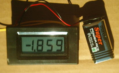
Here is an Example of this type of meter.
Problems: When using Digital Meters, you will never get a stable
"Zero" reading, Thus Off-Setting Small differences that can easily
be seen on an Analogue Meter.
Another Problem is that these Digital meter read Both Positive and
Negative Values, This can be VERY Confusing and give False readings.
So I DON'T really Recommend using these Digital Meters.
"A Better Alternative" would be a 25 or 50 uA Analogue Meter, But they are more expensive and difficult to find in a Small Size meter.
Final Mechanical Construction.
Most people have seen pictures of metal detectors. Theirfore I'm leaving the actual design of the mechanics to each person. However, If you need help, you can contact me for suggestions.
Single Coil Instructions
Only insert R17, Not R16! (Leave these holes empty) Connect Only L1 to the board at point "A" and the Zero Volt Trace. Total current draw from the battery should be about 100 Ma., but can be higher, depending on your particular coil.
Dual Coil Cancelling Mode Instructions
Only Insert R16, Not R17! Connect One coil at point "A" and the Zero Volt Trace, and connect the second coil at "B" and the Zero Volt Trace.
Total current draw will be about 150 Ma., But can be higher, depending on your particular coils.
For General Purpose detecting: Place these two coils Overlaping by 1/2 of there diameter.
For Pinpointing Objects: Place the coils "Side by Side", so there is an aproximate 2 inch space between them. Detection will now be in the area between the two coils.
Dual Coil, Seperate Recieve/Transmit Instructions
Only Insert R17, Not R16! Connect L1 to the board as normal at point "A". "Remove Jumper JX" and connect the second coil to the "Zero volt Trace" and to the pad "L2A" shown in the Overlay Photograph and on the Schematic.
Coil Placement: This is where the Fun Comes, Lots of Expermenting. Coils can be various different sizes and turns. They can be placed close together or far apart. Most changes will result in the need to re-adjust VR1 and your speaker tone pulse to the one pulse per second.
I suggest that the coil connected to "A" be a typical flat coil of about 30 to 40 turns and 8 to 10 inches in diameter.
The second coil, connected to "L2A" can be almost anything and can have more turns for a theoretical greater induced voltage. Additionally it should be shunted with a resistor, somewhere in the region of 100 ohms to 680 ohms. (or for ease of expermenting, a 500 Ohm Trimpot in series with a 100 ohm resistor) Beyond these Suggestions, Your On Your Own!
SETUP for Circuit
IMPORTANT: GET ALL METAL OBJECTS AWAY FROM THE COILS! It is a Good Idea to use shielded wire to the coil, as normal wires can also detect metal.
Once the circuit is operational, adjust VR1 for any voltage between 0 volts and .5 volt on pin 6 of IC9 at the test point. This Adjustment Will result in the Greatest Sensitivity of the unit. If you cannot do this you have a problem.
This Paragraph, Updated June, 2009 Than set VR2 for a slow beat Tone (50 to 300 Hz) in the Speaker and Finally, Zero the meter with VR4. (Changing VR1 again, Will affect both these adjustments) NOTE: The Exact Beat Tone is Not Critical. It Mostly depends on your ability to Hear Different changes in the Frequency tone.
Now bringing a metal object into the field of L1, you should hear an increase in beep rate! If you cannot do this you have a problem.
Coil shape and size will greatly affect sensitivity. A rectangle spiral is probably the most sensitive, But also the most difficult to make! ****Here's where the playing comes in!
Sensitivity: If your detector is working correctly you should be able to detect a "Pop Can at a "Absolute Minimum Distance" of "15 Inches" and "Hopefully even a greater distance, with a coil simular to the 8" flat coil that I use!
If Not, I would believe either you have a Poorly made Coil or a Problem on the Board! PROBLEMS....You can always E-mail Me! Please put "Metal Detector" in the "SUBJECT LINE"
All Imformation in this Article is "Copyright protected".
Chemelec
*Copyright © 2003 & 2012*