Created, 2004 Latest Revision, May 13, 2014
EFFECTIVE: AUG 1, 2010:
I will NO LONGER will give Any help to persons who did Not Buy
at least the Basic Kit of parts from me.
This is because, Too many persons make Substitutions or Errors, than expect
me to solve their mistakes.
**A Kit of parts Is Available from me.
And other than the PCB and coils, most parts are supplied at my Landed Cost.
When Purchasing this detector Kit from me, I will also send you a 8.5" X 14" Printed Schematic, as well as a 4" x 6" color Overlay Picture. Email Me for the Current Prices.
NOTES: This Pulse-2 has the Same Features as my Pulse-1, But with 3 additional controls for Varying more of the Parameters.
So the Pulse-2, "MAY" be an Improvement on my Pulse-1 Detector, "BUT ONLY IF YOU KNOW HOW TO PROPERLY ADJUST THE EXTRA CONTROLS". I Definately Do NOT Recommend this project for Metal Detector "BEGINNERS".
Changing R26 to a 33K may possibly give a better adjustment range for VR2. This Depends Somewhat on your specific Coil.
I wrote this Pulse-2 as a Seperate article from the Pulse-1 as it was getting too confusing. However most of the info in the Pulse-1 article will also apply to this Pulse-2 Detector So it would be a good idea to read the Pulse-1 article Also.
An Optional "Frequency Switch & Capacitor" is Available, to go from 100 Hz to 1000 Hz.
USE CAUTION: When using the 1000 Hz, Increasing the Pulse Width to full, Can Sustantially Increase Current Draw. Typical Current Draw at 100Hz is 90 to 150 mA, Actual Current depends on your coil. But at 1000 HZ and a High Pulse Width Setting, This Current can go Over 400 mA. This High Current will cause the Regulator and Mosfet to run Warm, possibly even HOT and Definately Reduce Battery Life.
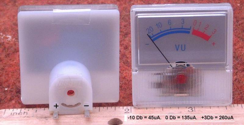
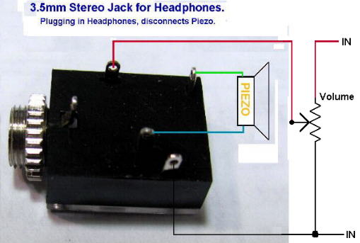
It has a Built in Switch to turn off the Piezo, When the headset is plugged in.
Warning: This Project is NOT FOR BEGINNERS
Before Testing the Completed Unit Wash the board to Remove All Flux Residue. IT WILL NOT WORK CORRECTLY IF YOU DON'T!
It is Also HIGHLY Recommended to use a Current Regulated Power Supply when first
testing this unit.
(Less than 200 Ma. is quite satisfactory)
Excessive Current (generating heat) will Distroy the REG1117A or the MC33269. Failing a Regulated Supply, a 60 Watt/110 volt standard light bulb can be placed in series with the positive battery. This should limit current to a reasonable level, preventing any damage to parts. Good Soldering and control wire Layouts is a Must!
A Note about the Battery:
I Do Not recommend using a Lithium Ion Battery on this detector,
because most are rated at 10.8 to 12.6 Volts.
When the battery goes below 11.5 Volts the detector will Lose Proper Voltage Regulation
And become Unstable.
I do Recommend using 10 NiMh Batteries will provide Better Power, because they Maintain
a Constant 12 Volt supply or use a 12 Volt Sealed Lead Acid Battery. (Gell Cell)
NOTE: It is Important to use a Good Soldering Iron, Rated at about 25 Watts
and having a Small Clean, properly Tinned Tip!
Note also the Revision Dates on All My Articles.

"CLICK HERE", I now have Flat Coils for sale!
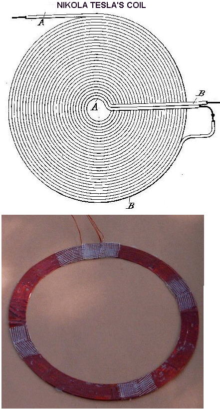
New Coil Design for the metal detector. This is a coil designed by Nikola Tesla, Patent 512340 Jan 9 1894.
"CLICK HERE", To see this Coil.
Although Tesla patented this coil long ago, it was before Metal Detectors were invented. His application was for Radio Transmission and it had problems because of Parastatic Capacitance. This is Not a problem with a PI Detector because of the much lower frequencies.
My test results show some increased Sensitivity using this type of coil on my detector. Especially on Smaller objects.
These coils require winding two seperate wires simutanously in a flat radial coil, than joining the wires to make the two coils in series, but out of phase with each other. Not so Easly to do.
But I do make some of these for sale. As some persons like to Experment with them.
Note: This metal Detector was Not specifically designed
to Detect Gold Nuggets but these added controls may help,
"If you can set them Correctly for your particular Coil".
But Do NOT Expect to find Tiny Nuggets or Gold Flakes.
**I have tried to make this article as complete as possible, but I will Not assume any liability for any "Errors or Omissions" in this article.
The 3 possible coil Configurations are:
1) First configuration is just a single coil. Good for most applications!
2) Second is a dual coil, with noise and ground effects cancellation.
3) Third is a dual coil, one for transmit and one for recieve.
My Recommended Optium Flat Coil Sizes using 20AWG: But Depending on my current Stock, I may also use a 20, 21 or 22 AWG.
Really Small Objects: ID = 2.62 inches & OD = 6 inches with 52 turns. Coils wound on Ferrite Rods are also good.
Medium Objects: ID = 5.8 inches & OD = 8 inches with 34 turns.
Its Best to use this size coil for finding Coins.
Large Objects: ID = 8.2 inches & OD = 10 inches with 28 turns ID = 10.4 inches & OD = 12 inches with 25 turns. ID = 13.6 inches & OD = 15 inches with 21 turns. ID = 39.2 inches & OD = 40 inches with 12 turns.
Sept 5 2004
Just for Curosity, I made a "Coplanar Coil" Consisting of 26 turns on the transmit and with almost 7 turns on the Null Coil. The Recieve coil was 112 Turns for hopefully better signal detection.
I Very Carefully Nulled the coil with my scope and signal generator, Than connected it into my circuit as a Seperate Recieve/Transmit configuration.

To My Disapointment, After All that Trouble of making it. It was Not as good in Sensitivity as my flat coils of the same size. It also suffered considerably from ground effects, However I didn't use a faraday shield on it, Which would definately help.
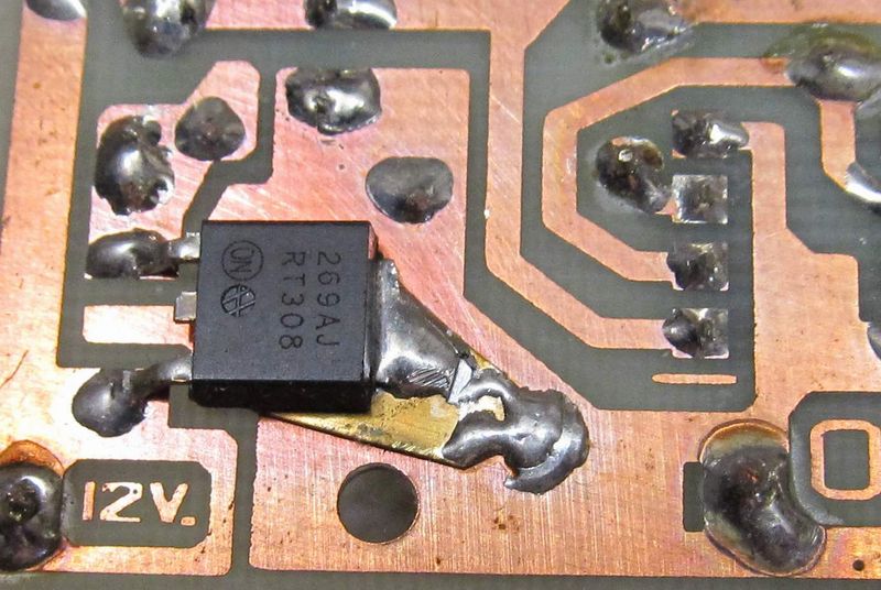
Mounting the REG1117 Regulator on the Copper Side.
*** Be Careful that you Do Not Over Heat it. ***
As shown in this picture, I usually put a small Brass Shim under this part,
but it is not necessary for you to do this.
***********************************************************************
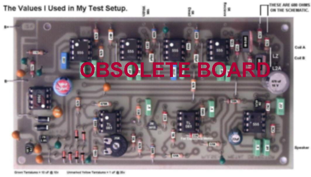
 OLDER, Picture Overlay of the
Assembled Circuit Board.
A Clear Revised Picture and Schematic will be Included in the Parts Kit.
Pictures of My Metal Detector Project,
Built by Other Persons.
It would be Greatly Appreciated to recieve Feedback
from ALL persons building this Detector.
As of May 2010, Well over 2000 of this detector have been built,
and From Replies recieved no one has been unsatisified with it.
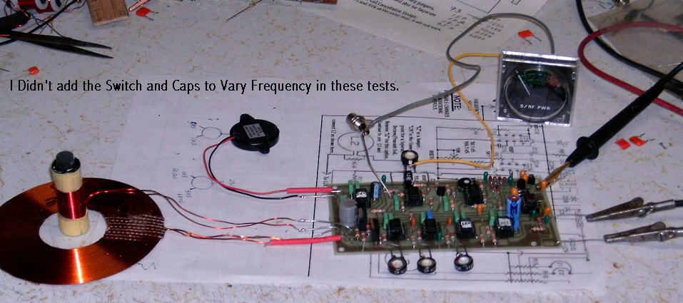
My Test Setup, For a Dual Coil,
With Seperate Transmit/Recieve Coils
With This Setup, but with these coils adjusted on a Same Plane (Large coil Raised up
Even with top of Ferrite Core on the Smaller coil, I can detect a 1/2 Gram Nugget at
1 1/2 inches. And close to 3/4 of an inch on a 1/4 Gram Nugget
Wish I had a 1 Gram nugget to do tests on that also. Anyone Willing to send me one?
Update: Same setup, but with More turns of smaller wire on the Recieve coil only,
Now detection is a bit over 2 inches on that 1/2 gram nugget.
Explainations, Calibration
and Setup Procedures
ADDITIONALLY, Remember This:
THE MOST IMPORTANT THING WITH ANY METAL DETECTOR, IS THE OPERATORS "ABILITIES", "SKILLS" AND "PATIENTS" in using it PROPERLY!
Chemelec *Copyright © 2004, 2012*
*Copyright © 2004, 2012*