Peltier or TE Devices

Preliminary Article, Created "Nov 23, 2005"
Latest Update: Jan 23 2015, New "One Can Pop Cooler".

Over the past 40 years I have played with many of these devices and created Numerous Designs.
Although there Efficiency is not very good, they can be used to create practical water coolers and
small coolers for food products.

Typically TE Modules can obtain a 40 Degree Celsus Temperature Differential, Between the Hot side
and the Cold Side. This Temperature Difference is Actually at the Surface of the Module.
Not at the heat sink or Surrounding Air Temperature.

A Real Refigerators is very difficult as the temperature inside relates to the Ambient Air
Temperature and the Actual Heat Sink Temperature.

It is Very Difficult to maintain: typically about 4 Degree Celsus as is needed in a refigerator.
Although using a Small Cold Plate, you can cause Ice to form on it.

The Biggest problem occurs when trying to use these devices in a Vehicle. On a Cool Day, No Problem.
But on Hot days the temperature inside a vehicle gets Really HOT.
Easily to 40 Degree Celsus (122 Degree Fahrenheit) or higher. Thus trying to keep the Heat sink Cool
is Very Difficult.

Some of my Experiments

1) Initially I played with the idea of using Pulse Width Modulation (PWM) to control these devices.
This is NOT a good way to go. TE Devices do not like Pulsed Frequencies much and the Efficiency goes Down.

2) I also experimented with the idea of Controlled Power, so as the Fridge got colder, FEEDBACK caused
the Current to Decrease proportionally, thus attempting to maintain a constant temperature.
This also does not work well as lowering the current on the TE Devices results in Poorer Efficiency.
It is Much more Efficient to turn the TE module, "Full On" or "Full Off", as needed.

3) Due to Thermal Conduction, Adding a controlled door on one side to prevent heat loss when the module
is off. This can be Quite Effective in maintaing reducing losses.

4) I have used both water and air cooling. Water cooling is far more effective, if you have a Large
Quantity of water and a low power pump. But this is not too practical in a vehicle.
I even buit my own pumps using small Cassette type motors.

5) More to come.

Some Practical Application info:

1) Good Thermal Contact on both sides is Essential.

2) Maintaining a Good Contact Pressure on the TE Module.
This is important because of Thermal Expansion and Contraction that results on both the module and the
Heat Sinks.

3) Since these modules are typically about 1/8 to 3/16 inches thick and you don't want the heat to transfer
from the Heat Sink to the Cold Sink, An Additional Spacing on the Cold Side is needed.

4) As Previously Stated, I believe Full Power or No Power is Best.

5) Using Mosfets for Control is Probably the Best way.
Relays can be used, but contacts can become Pitted ad relay coils wasted power.

6) Another Problem occurs on Turn Off: Residual Heat in the Heat Sink now transfers back to the cold side.
So Ideally the Cooling Fan or water cooling, will continue to cool the Heat Sink, for a Brief Period after
turning off the module.


Below are some General Pictures.
And I will post a Temperature Control Circuit in the future.


Some of my Peltier Devices.

A water Cooled Module I made.

A LARGE Heat Sink.

A Water Heat Sink I Made.

A Water Heat Sink I Made.


My "One Can Pop Cooler" Project.

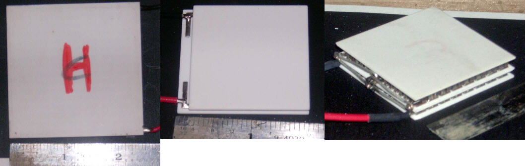
The Thermoelectric Module (TE) in this Cooler is rated at 6 Amps with 14 Volts DC.
This final Unit Cools a can of pop, Quite Quickly.

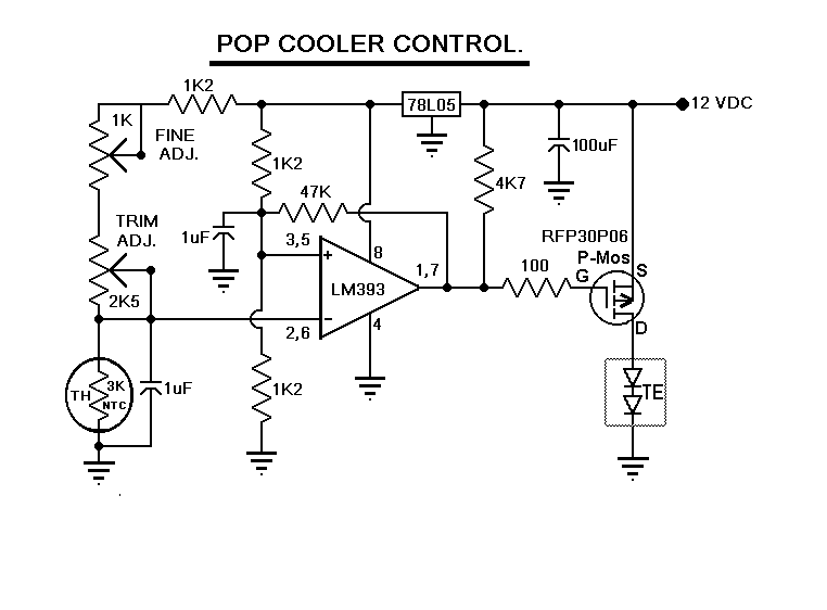
My Control Circuit for Heat Sink Temperature.

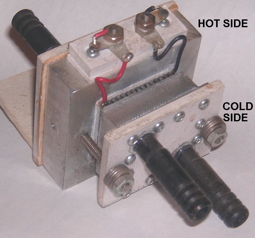
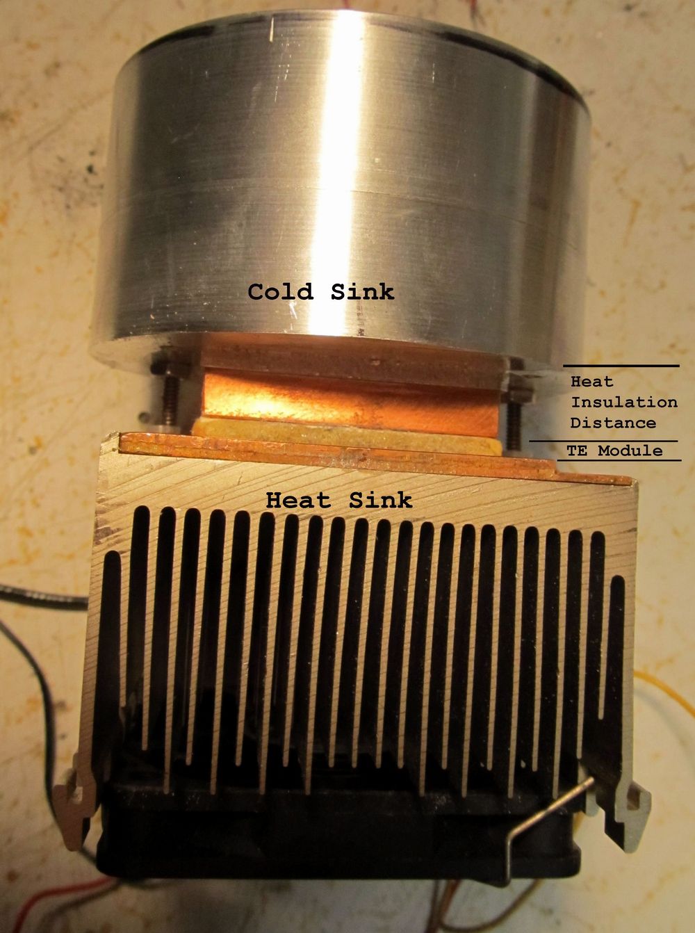
My First Proto of a Single Can Pop Cooler.
But I didn't machine out the Cold Sink for a Proper Insulation Distance.
So I Had to add a Copper plate for More Distance between the Cold and Hot Side
to give Better Insulation Distance.

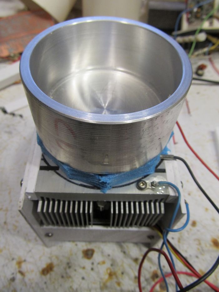
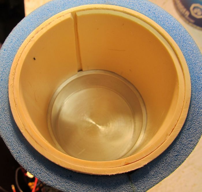
"New", Single Can Pop Cooler with Properly Machined Cold Sink.

Gives Good Cold and Heat Conduction and insulation layer between them.
Blue Wire on Left Side is to the 3K Thermister.

Single Can Pop Cooler with Properly Machined Cold Sink.

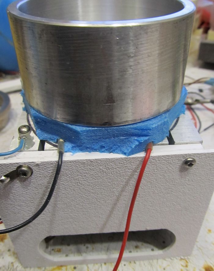
Sorry I Didn't take a Picture of this before I Assembled it.
This is now the Same Insulation Distance but Machined in the Aluminum
and Gives Good Cold and Heat Conduction and insulation layer between them.
Blue Wire on Left Side is to the 3K Thermister.

Top View.

The Assembled Circuit Board.

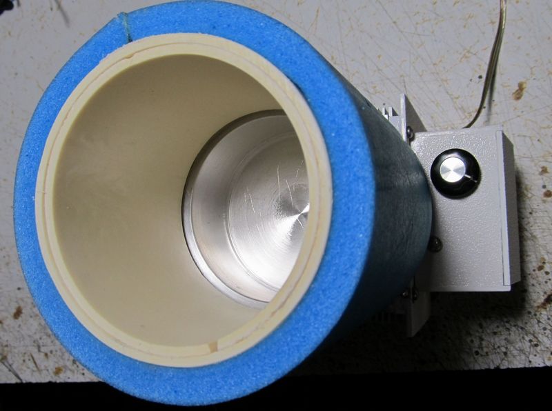
Note: This was the Prototype and the 1K Trimpot is a Full Size Pot on the Cooler.

Bottom View.

Another Top View, Showing the 1K Temperature Control.

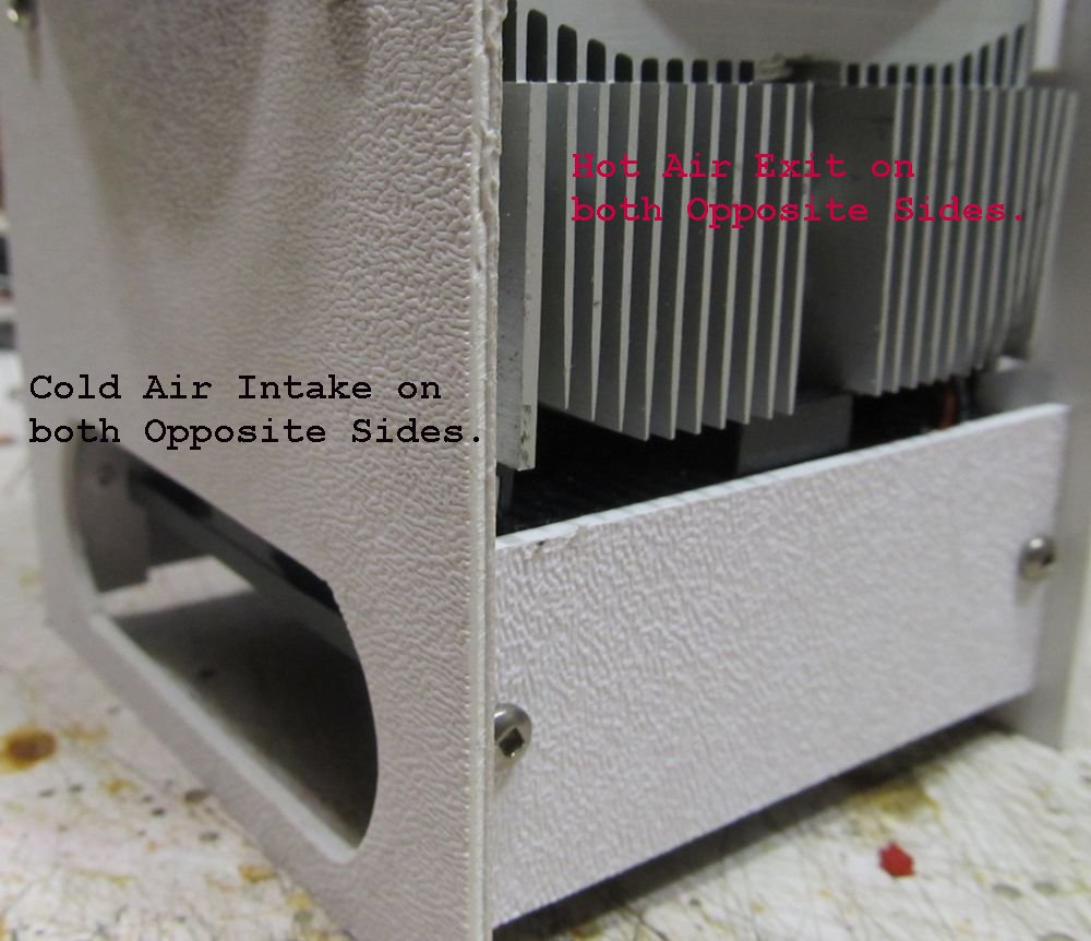
View of Cold Air Intake and Hot Air Exit.

These are on Opposite 90 Degree Sides to help Reduce the Hot Air that Exits
from directly entering the Cold air intake.

Possibly more to come

"Go Back to my Projects Page"

I assume all the info in this article to be correct,
But I assume NO Liability for Errors or Injury in making this or any of my projects.
BUILD THEM and USE THEM AT YOUR OWN RISK.


All Imformation in this Article is "Copyright protected".

Chemelec

*Copyright © 2005 & 2015*