In this circuit I have used a Rotary Switch to select Various Current ranges as a Potentiometer is not very practical for the lower resistance/High Current Ranges. But if you wish to change it to a pot, you can try it. ** It is practical to use a pot on the lower current ranges so the lowest switch range could be a pot with a small series resistor. Allowing for adjustment from say "10 mA to 500 mA". Than use fixed resistors on the higher current ranges.
This circuit will give you a Very Simple, but a quite versatile Voltage and current regulated Supply. And Down to "Zero Volts" out is a Nice Feature.
I recommend in making two of these. This will allow for "Plus and Minus" supply voltages, when needed. They can Also be Paralleled or placed in Series for Higher Currents or Higher Voltages, As is Sometimes Needed.
The Output is reasonably short circuit protected if suitable heat sinks are used and this supply should go down to Zero or very near Zero Volts.
Output Voltage and current depends somewhat on the transformer used, as well as which Regulator used. You have a choice of an LM317 for 1.5 amps Max, or an LM350 to give about 3 amps Max.
I Haven't tested this, But an LM338 should also work for even Higher Currents. The LM338 is rated at 7 amps peak or 5 amps Continuous.
The LM317 has an Maximum Differential In to out voltage of 40 Volts Maximum. The LM350 and the LM338 only have a maximum Differential, In to out voltage of only 35 Volts Maximum.
All of these LM317, LM350, LM338 chips in this circuit REQUIRE SUITABLE HEAT SINKS. As they would also in any other high current power supply.
Output Voltage is a function of the transfomer supply and can be as high as about 35 volts for the LM317, or30 Volts for the LM350 or LM338. Although I don't recommend it as Power Dissipation in the Regulators can becomes Quite Excessive.
For the LM317, DO NOT EXCEED A TRANSFORMER RATING OF 56 VOLTS
CENTER TAPPED. And FOR ADDED SAFETY, I WOULD SUGGEST NO
HIGHER THAN 50 Volts Center Tapped. (25-0-25)
For the LM338 or 350, DO NOT EXCEED A TRANSFORMER RATING OF
50 VOLTS CENTER TAPPED. And FOR ADDED SAFETY, I WOULD
SUGGEST NO HIGHER THAN 48 Volts Center Tapped. (24-0-24)
This Circuit Can also be made to operate Without a Center
Tapped Transformer, if you only use Half Wave Rectification.
But it will suffer in quality.
"T1" Should also be "Appropriately Fused".
Transformer "T1" needs to be at least 1.5 times the "rated output current" to allow for Filtering losses. If not, it will run excessivey hot under full load conditions. In all rectifier filtering situations, a significant amount of current is lost through the filter capacitors.
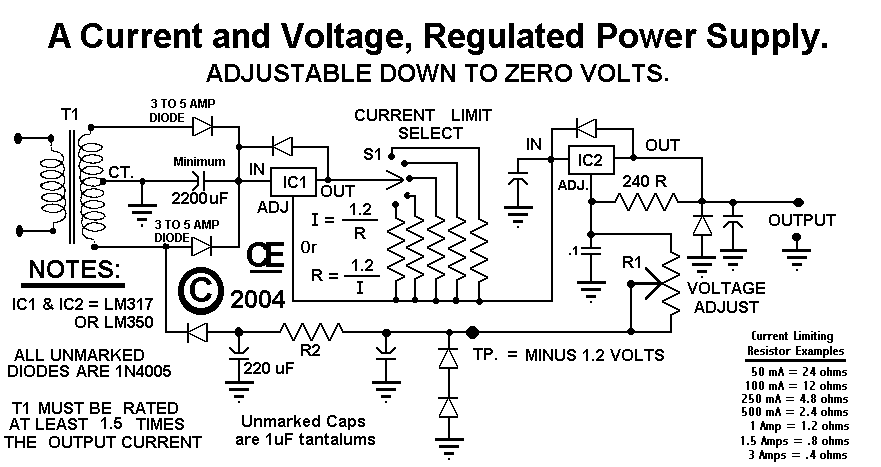
T1 is a Center Tapped transformer, followed by two diodes to give a Full Wave Output. An additional diode is used to generate a Minus supply to allow the supply to go to zero volts. NOTE: A Non-Center tapped transformer with a full wave bridge rectifier WILL-NOT Work in this circuit. If you want to do this, you will need a Small, Second transformer for the Minus supply
I would recommend building this supply for around 15 to 18 volts out. That will usually cover most project applications and keep power disipation levels of the regulators to a more reasonable level.
NOTE: R1 is calculated by the formula: R1 = (((Volts x .8)-1) x 240) However since Potentiometers come in limited sizes, I would suggest:
1 K Ohm Pot = Aprox 0 to 6 Volts 2 K 5 Ohm Pot = Aprox 0 to 14 Volts 5 K Ohm Pot = Aprox 0 to 27 Volts
Note: Over sizes Resistance Pots will just result in no change of the voltage at the higher resistance.
NOTE: R2 is determined by the voltage across the 220 uF Cap.
(Volts - 1.2) R2 = ------------- .015 Any Resistor close to the calculated value should be fine. Its only purpose is for an approximate 15 mA current flow which will create a quite stable -1.2 volt supply.
The PCB is designed for "Moderate Current outputs" with the "On Board Heatsinks". For HIGH CURRENTS, I recommend "Off Board regulators and Large Heat Sinks".
Or An old "Computer Fan" may be used for cooling to allow for high currents with the on board regulators and heat sinks.
On the Proto, I used a Mediun sized T0-220 Extruded Aluminum Heat sink. But I also designed the board to allow for a fairly Large one "THM7396".
On the Proto Board:
There are Provisions for the Current Resistors shown on the Schematic. Since some of these are Uncommon Values, The PCB shows values to create these fairly close. Use 1/2 watt or better yet, 1 watt resistors. SI mounts Off the Board.
I Also Recommend that the Current Limit Resistors and Power Diodes be placed about 1/4 inch from the board. This allows for better cooling and will prevent damage to the PCB if they do become hot.
I used 1N4005's for the rectifiers and a 36 volt Center Tapped Transformer. My Output Voltage was adjustable from Zero to 24 Volts at lower output currents and zero to about 20 volts at 1.5 amps. Obviously the 1N4005's, being rated at only 1 amp were running very hot at this time. I even cranked it up to 6 Volts @ 2.5 amps output for a few seconds, without failure. I Don't recommend you try this
For 3 Amp Diodes, I recommend "1N5400's" For 6 Amp Diodes, I recommend "Diodes Inc", Part number "6A05DICT" Both of these diodes are a 50 Volt Ratings and should cost under $1.00 ea..
One Final Note:
Although I used 1 uF tantalums in 5 places, some or all of these can be
replaced with good quality .1 uF Caps. This will work Equally well.
"Back to My HOME Page"
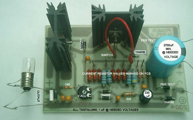
Prelimimary Assembled Circuit Board, It Works. I am using a Jumper Wire in place of a S1, obviously you will want a switch. Also I only used 1 amp diodes for testing purposes here.
"I Assume No Liability from the Construction or Use of this circuit"
Build and Use it at your own risk!

All Imformation in this Article is "Copyright protected".
Chemelec
*Copyright © 2004, 2007*