"Coil Inductance and Internal Capacitance
Go Back to My "Home Page"
Or
Go Back to My "Projects Page"
Preliminary, Created: Feb 1 2006
I Decided to Check my coils for Inter-wire and Total Capacitance.
It is a Well Known fact that Internal Capacitance in a coil reduces its frequency response.
In the Tests Below, The coil Lead Lengths on all coils was about 5 inches.
No Coax cable used.
Once you have determined the Free Air Resonance, you can guess at appropriate capacitor
values and put them into my LC Calculator.
When you get the correct value of capacitance, the answer will Equil the Resonant Frequency,
And that capacitor value will be the Total Capacitance with-in the coil.
Most of this Capacitance is "Inter-Wire" Capacitance.
Assuming you have put your coil Far away from any objects, Only a Small Amount of this
will just be Stay Capacitance to surrounding objects.
In doing these tests, I Hung my coils from a piece of string, Two Feet away from any objects.
"Here are some Coils I tested."
Radial Coil 1, Round Shape:
Diameter 11.5 inches.
Turns = 23
AWG = 20.5
Measured Inductance = 316 uH.
Free Air Resonance = 1,825 Khz (1.825 Mhz)
Resonant Frequency with Paralled 100 pF Cap = 814 Khz.
Radial Coil 2, Round Shape:
Diameter 12.25 inches.
Turns = 26
AWG = 20.5
Measured Inductance = 421 uH.
Free Air Resonance = 1,585 Khz (1.585 Mhz)
Resonant Frequency with Paralled 100 pF Cap = 700 Khz.
Radial Coil 3, Oval Shape:
Dimensions 4 Inches X 10 Inches.
Turns = 46
AWG = 20.5
Measured Inductance = 310.6 uH.
Free Air Resonance = 2,540 Khz (2.54 Mhz)
Resonant Frequency with Paralled 100 pF Cap = 851 Khz.
"CLICK HERE", For my "LC Calculator"
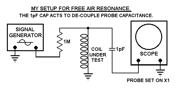 My Setup to measure the Free Air Resonance.
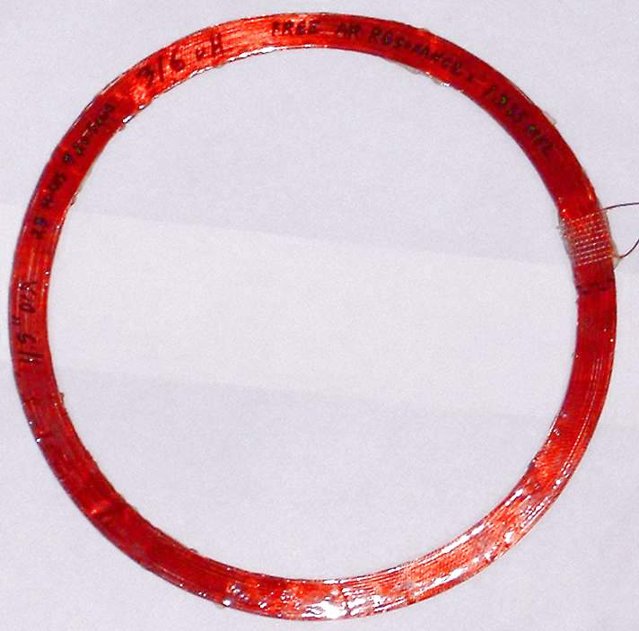 Picture of Coil 1.
MORE INFO TO COME LATER.
All Information in this Article is "Copyright protected".
Chemelec *Copyright © 2006*