Created: Nov 15, 2005

Updated: Feb 14, 2018
About this Circuit:
This SPL meter will allow for a broad range of Sound Intensitity Tests.
The 4 Transistors near the middle of the schematic, Basically make an Integrated Circuit, Op-Amp.
I Specifically built it this way, as it really isn't much bigger an IC and these are very common transistors. Also, Cheap and easy to purchase.
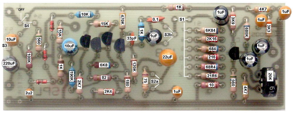
Sometimes 1% Resistors are not easy to find, So If you want to: You can Substitute: 22 ohms for the 21.6 68 ohms for the 68.4 220 ohms for the 216 680 ohms for the 684 2K2 ohms for the 2.16K 6K8 ohms for the 8K84
It will produce a Small Error. But generally not a problem for Normal Use.
Additionally, I Specify the use of a number of Tantalum Caps. These will the give Best Results.
However you can use Electrolytic types for some of these. But I Definately Recommend Tantalums for the Three, 10uf tantalums on the Supply Line.
If you use a Different Meter than the 135 uA one, You will need to Change the 100K resistor to something appropriate. With the 100K resistor, the meter Will give a Nominal 2/3 Scale reading. When it falls to about Half Scale, the Battery Should be Replaced.
Typical Operation: 1) It is always a good idea to start on the Highest Range and than go downward to get a reasonable reading. This Avoid Pinning the Meter and possibly damaging it. 2) It is usually best to use the Slow Range. This Also helps Pinning the meter. 3) The final case design is up to you, But Typically the Microphone should come out at a Point, Somewhat in a Cone Shape. This is to avoid Reflections of sound, hitting it from the case. 4) Try to use a Meter, Simular in Sensitivity to the one described in the schematic. I also did test this on some other meters, (up to 300uA) with varying results. 5) It would also be possible to connect this to an LM3916 Bar/Dot Display, dB Meter. But Current draw would be Considerably Greater on a 9 volt Battery. 6) The "C" Weighting Curve is fairly Uniform over the frequency range of about 30 to 10,000 Hz. (Depending on how well you Duplicate my circuit.) 7) The "A" Weighting response responds primarily to frequences between 500 to 10,000 Hz. This is Typically the range of Greatest Sensitivity of the Human Ear. 8) Note: Room Acoustics can easily change Sound pressure levels, by dampening certain frequencies. Moving around a room can Drastically change readings. So can your Body, as it can absorb sounds. 9) I also incorporated an output Jack. It can be connected to an Oscilloscope or Oher Test Equipment. Also to a High Impedance Ear Phone, to Listen. 10) The Speed Control can be set to Fast or Slow. Depending if you want to see a "Peak" or Averaging Response. 11) Maybe More Info Later. Calibration: Without having a Calibrated Meter, You will Just have to Guess at this. When "A" Weighted An Average Residance is about 45 dB., But that is Below the range of this instrument. (Although it could be Modified to go a greater range.) Background Music is about 60 dB. Typical Conversation is about 65 dB. A Loud Orchestra is about 80 dB.
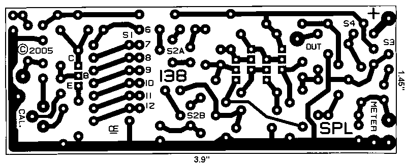
This Circuit Board for this is available. Email Me for the Current Price and Shipping Cost.
Chemelec
*Copyright © 2005 & 2018*