Origional Design "2002"
Latest Update "August 9, 2016" Added Overlay Picture.
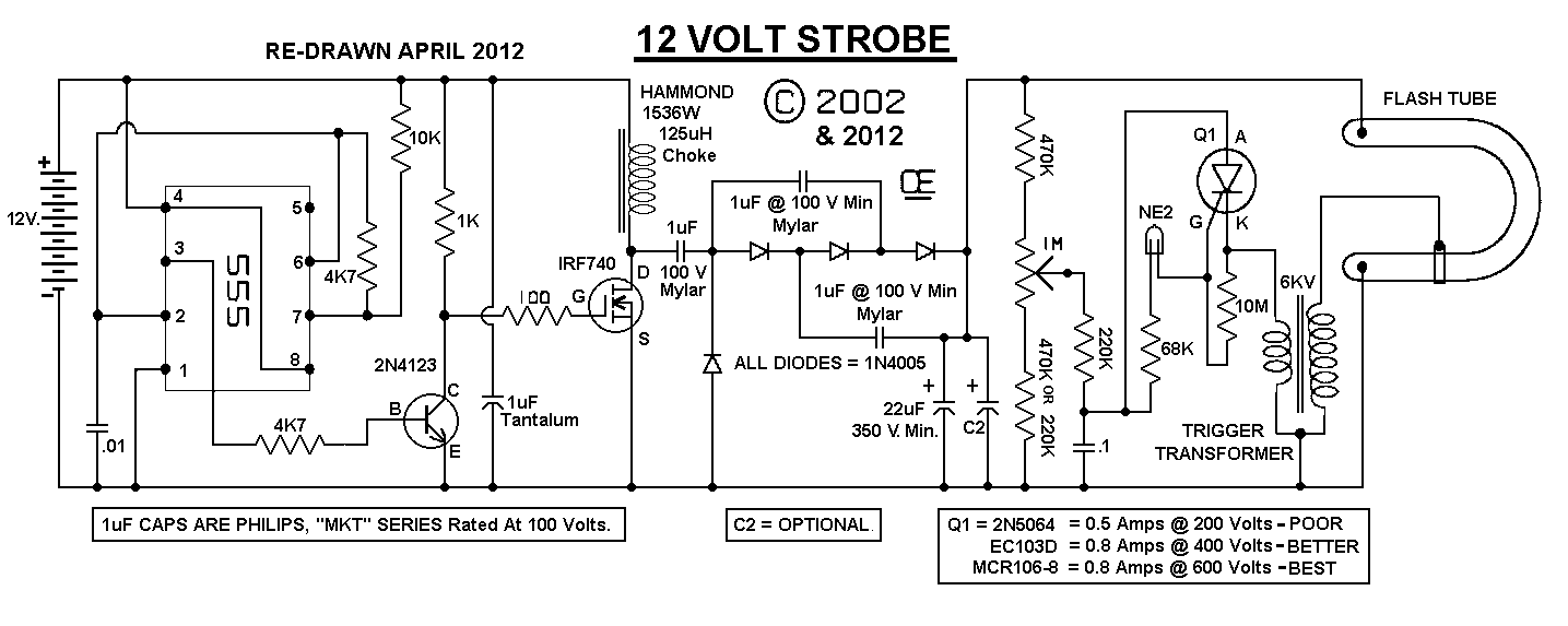
This circuit will give provide a Good Strobe Effect for a variety of Portable Uses.Nominal current draw is "up to about" 1 amp at 12 volts. Depending on value of capacitor on pin 2 of the 555 and the particular choke that is used. The .01 cap on pin 2 of the 555 may be slightly changed in value to optomize the output drive to the 22 mfd capacitor.
L1 is a 125 Uhy choke, rated at 3.5 amps. It is possible to substitute other chokes, but they must be capable of at least a 1 amp rating. Inductance value isn't too critical. Anywhere between 100 and 500 Uhy. should work fine. Of the ones I tested, this one worked the best.
There is a provision for "Two storage capacitors" on the board. You could use one or two of the 22 Mfd or two 10 uF. I had the extra space on the board and thought this might be a useful feature. I have tried this unit with a total capacitance of 320 uF at 200 volts. Not a fast repetive flash, (about 1 per second) but sure was "BRIGHT." However the larger the Capacitor, the shorter the tube life. The Tube supplied in the kit below is rated at 4 Watt-Seconds at a typical voltage of 300 volts and has an estimated life expectancy of 1,000,000 flashes, when used at one flash per second.
For those who build there own unit, This design should work fine with any of the small trigger coils, either 3 or 4 terminal types and most flash tubes that are available. On the Origional Proto, I just used some from my junk box and had no problems with any of them. And I have also tested it with 3 totally different coils and a few different flash tubes.
Doing a little research
My understanding of wattage ratings for these tubes is measured in "Joules". And according to the "ARRL Handbook", a Joule is one watt-second.The formula they give is: Watts = Volt squared, times Capitance in Farads, divided by 2
However the Capacitor in a Strobe circuit doesn't discharge to Zero Volts. The Minimun voltage I measure is around 110 volts.
Therefore, assuming a slow flash rate and achieving a charge voltage of 340 volt with a capacitance of 160 uF, (.00016 Farads) I come up with a wattage of:
340 - 110 = 230 volts drop.
230 times 230 = 52,900
52,900 times .00016 = 8.464
8.464/2 = 4.232 Watts Dissipation.
The tube shown in the picture of my proto has a 4 watt-second rating, with a life expectancy of 1,000,000 flashes.
I am not 100% sure on my evaluation of this, but it sounds logical to me. If anyone has other info, I'd be interested in seeing it.
Here is a letter from a reader, as written: This is a "copy and paste" of the e-mail! *************************************************************************** Nice site! I saw your explanation for the energy dissipated in a flash tube: My understanding of wattage ratings for these tubes is measured in "Joules". And according to the "ARRL Handbook", a Joule is one watt-second. That is correct. The formula they give is: Watts = Volt squared, times Capitance in Farads, divided by 2 This is the energy in a given capacitor. However the Capacitor in a Strobe circuit doesn't discharge to Zero Volts. The Minimun voltage I measure is around 110 volts. Therefore, assuming a slow flash rate and achieving a charge voltage of 340 volt with a capacitance of 160 Mfd, (.00016 Farads) I come up with a wattage of: 340 - 110 = 230 volts drop. 230 times 230 = 52,900 52,900 times .00016 = 8.464 8.464/2 = 4.232 Watts Dissipation This is not correct. You need to think in energy as stored in the capacitor. The capacitor starts out at: 340x340 x .00016 = 18.496, / 2 = 9.248 Joule And it ends up containing: 110x110 x .00016 = 1.936, / 2 = 0.968 Joule Thus, when the C discharges, 8.28 joules 'disappear', and not the 4.232 that your calculation shows. 52,900 times .00016 = 8.464 8.464/2 = 4.232 Watts Dissipation Now you could think about losses in the capacitor. That is energy that will not reach the tube. Another way of going about, if we think most of the losses are in the capacitor, and inductance does not play a role. This will be a lower limit on the energy: Let's say the voltage on the tube if it is conducting is 160 volts. The C goes from 340 to 110 volts and is 0.00016 F. That is a charge of (340-110) * 0.00016 F = 0.0368 Coulomb. 1 coulomb is the charge represented by 1 ampere during 1 second. A capacitor of 1 F charged to 1 V holds a 1 C charge. The voltage at which this charge is dissipated is the guessed 160 volts. Not really, as you and at 110, but it must be higher that that. 0.0368 C * 160 V = 5.888 J. Now, 1 million flashes is quite a lot. Good luck with the site! and a happy new year whed from Amsterdam, Thomas Tonino ****************************************************************************
2) For those interested in this Strobe for use on Model Planes,
The Total weight of my proto, including Flash tube is 1.75 ounces.
Part Kits are Available,Email me for Current Prices.
The PCB Only is also available, Email me for Current Prices.
NOTES:
1) The IRF740 mounts on the copper side, Possibly eliminating the need for heatsink.
A COMPLETE KIT OF ALL PARTS, NOW AVAILABLE!
** This Kit is First Quality Parts, Unlike a lot of the cheaper kits that
are made up of cheap surplus parts they are trying to clear out.
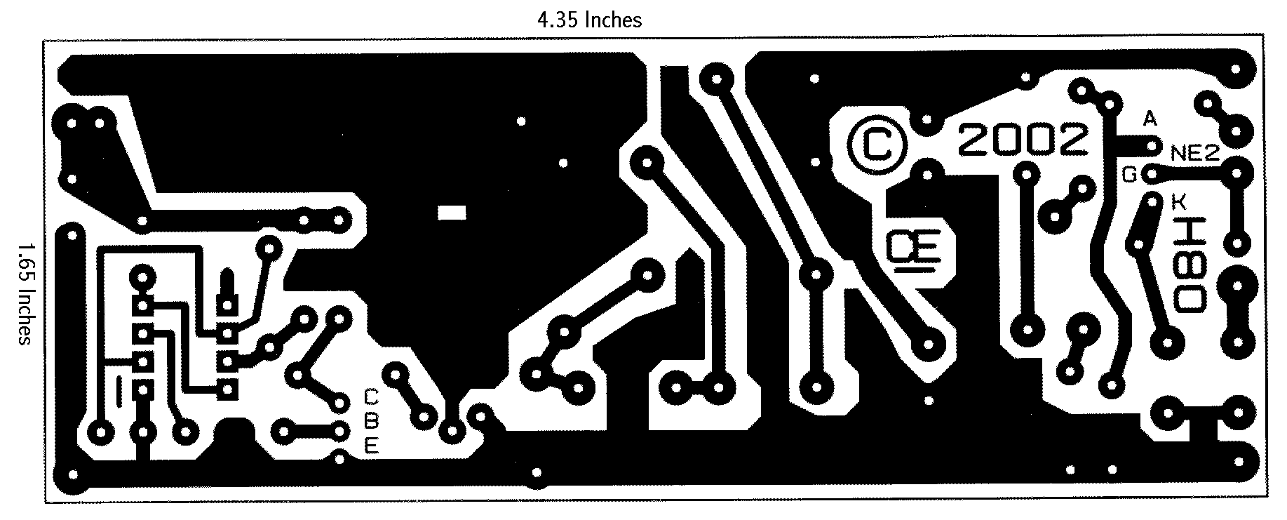
 Strobe "Parts Overlay and Parts List"
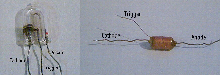
"Pinout of Bulb and Trigger Transformer"
Strobe "Parts Overlay and Parts List"
"Pinout of Bulb and Trigger Transformer"
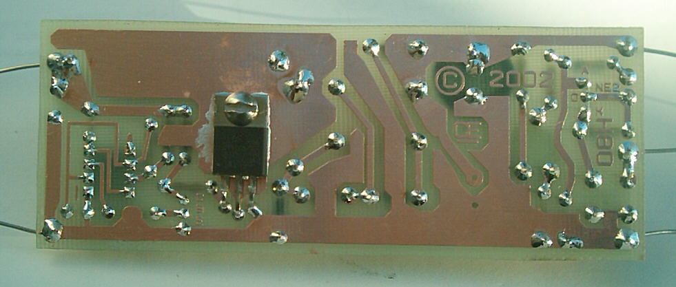
Photo of the unit
The Trigger Coil May be a differet Style to the one shown in this Picture.

Parts Overlay Picture.
The Trigger Coil May be a differet Style to the one shown in this Picture.
Chemelec
*Copyright © 2002 & 2016*