"I DO NOT RECOMMEND ANYONE BUILD THIS DEVICE".
This Is Presented HERE, Only for the Purpose of Demonstrating:
"How Simple a Deadly Device can be Constructed".
And If you do NOT Understand the Construction Details Give Below, You
are DEFINATELY Not Understanding enough to Even Attempt Making it.
I WILL NOT Offer any Further Construction Details.
NOR WILL I ACCEPT RESPONSIBILITY FOR THE STUPIDITY
BUT IF YOU DO SO, IT IS TOTALLY AT YOUR OWN RISK.
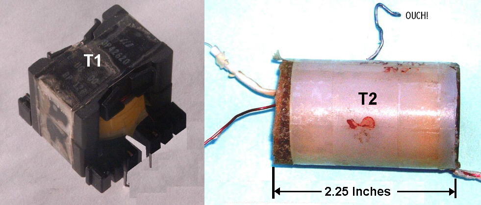
"T1" Was Home Built using a "Magnetics" Ferrite Core # "42620" and a Bobbin # "PCB2620-12".
T1 can also be built using a Magnetics Pot Core, OP42616-UG and the PC-B2616-11 Bobbin.
I Usually have Stock of Both of these.
WINDING T1:
The Primary Consists of a Dual 18 Turn Bifular wound coil using #26 AWG Wire.
It requires 2 layers, with "Nomex" Insulation between them, As well as a layer of Nomex over the Primary.
The Secondary Consists of 8 Layers of 40 AWG Double Insulated Enamel wire
with aproximately 40 turns per layer,
Additionally a .003 Inch thick "Nomax Paper Insulation" is Placed between each layers.
Before Assembly, the Ferrite core is Gapped to 5/1000 of an inch.
"Nomex:" Is one of many Special Insulator types of paper used in the Transformer Winding Industry.
Alternately you can use other Insulators such as "Fish Paper", Although they are Not as Good.
With this Transformer Connected In the Circuit as Shown, Current draw is about 250 Ma at 12 volts With NO LOAD.
With the Diodes, Caps, SCR and T2 connected in a Compete Circuit, "The Current draw can Exceed 2 Amps".
EVEN MORE POWER: A Bigger T1 Can be made Using a 42625 Core and a PCB2625 Bobbin.
The Primary Consists of 14 Turns Bifular Wound on Two Layers.
Change the Secondary Wire to a 38 AWG, Double Insulated Wire and use about 45 turns per layer.
Fill the Bobbin with as Many layers as Possible, leaving a bit of Clearance between the last layer and the ferrite core.
The Gap Remains the Same at 5/1000 of an inch.
This Results in a Faster Charging Time and a Higher Supply Voltage.
"T2" Was Wound on a "Fair_Rite" Rod, # "4077375211". It Measures .375 OD by 2 inchs long.
I Stock Both these Rods above.
But now I Only have a few of the first one above,
And a few more of the second one.
(I will see about getting more now, but typically
these suppliers only sell in LARGE VOLUMES.)
WINDING T2:
First Apply a layer of .003 Nomex Paper Insuation.
Now wind a Primary of 25 Turns, 22 AWG wire in a single Layer.
The Secondary is wound over this with 40 AWG, Double Insulated Enamel Wire and aproximately 180 turns in the first layer
This Completed Transformer is than Submersed in Epoxy, (Ideally in a Plastic Form to contain it around the transformer.)
and than placed in a "VACUUM CHAMBER" and Subjected to a high Vacuum of at least 25 inches of Hg.
for a one or two Minutes, than Release The Vacuum. I usually Repeat this Vacuum Process Two or 3 Times.
The Reason for this is to Remove all Air Bubbles and have the Epoxy Totally Penitrate between the Windings.
The Epoxy Surrounding the transformer should be at least 1/4 inch thick over the Outer layer and 3/8 inch over the Ends.
Even though Epoxys have Different Hardening Times, such as 5 Minutes, 15 Minutes and some "up in the Hours",
They Actually Require about 24 Hours for a "FULL HARDNESS".
SO DON'T RUSH THIS!
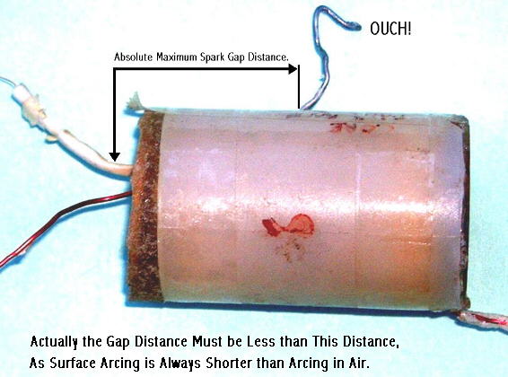
Spark Gap Distance
The Correct Spark Gap Distance is Essential in the Completed Unit.
The Maximum Distance is a Function of How Well You Made T2.
Too Great of a Spark Gap Distance and T2 Shorts Out, Internally or Externally
NOTE: Some Info May have been Omitted in the Above!
This was My Prototype and I will Not Responsible
for any "Errors or Omissions".
A Real Misconception about Stun-Guns, Is the Voltages.
It Sound Good in the Advertisements, But it is Current that does the damage.
The Pulsing Effect of the Stun Gun adds Enormously to the Effect, But any spark capable of
pentrating through the clothing and Surface Skin is totally sufficant to do the job of Penitration.
A blue spark looks pretty, but a yellow spark is
MORE People are Killed by Relatively LOW Household Voltage
than any other electrical supply.
Points to Ponder,
REMEMBER: In Reality, the spark gap determines the "Actual Voltage Available at the
probes".
With a spark gap of 1 to 2 inches or so, it may be No-where near the 100,000 Volts
And DIFINATELY NEVER the 750,000 volts that these manufacturers make claims of.
IF YOU REMOVE THE SPARK GAP, it MAY Attempt to Attain these Voltages
But in the Process it will short out across the surface of T2.
OR INJURIES, RESULTING FROM PERSONS ATTEMPTING
TO BUILD OR USE THIS DEVICE.
Centered on each layer so there
is a dead space on either side. This Prevents possible arcing.
"ANOTHER T2" Was Wound on a "Fair_Rite" Rod, # "4077312911". It Measures .315 OD by 1 1/2 inchs long.
Both these are Material 77 and it worked EQUALLY WELL.
But If you think All Ferrite Rods are the same and you can Just use Any Ferrite Rod,
THINK AGAIN, "YOU ARE BADLY MISTAKEN".
It is than covered with a .005 or .008 Nomex Paper insulation.
The .008 Nomex is a bit better to keep this Layer more even to wind over.
and than LAYER Wound in declining layers at about 10 turns per layer.
A layer of .003 or .005 Nomex is placed between Each Layer.
1) 400
2) 390
3) 370
4) 360
5) 350
6) 340
7) 330
8) 320
9) 310
10) Final Layer about 125 Turns with the Output taken off Directly in the Middle, Lenghtwise.
And a Final Couple of layers of Nomex are placed over top and Taped in place.
Total Turns, About 3,675 turns. But the Exact number of turns is Not All that Critical.
The Absolute Ideal is to "Pi" Wind the Secondary, But this Results in a Different number of turns and only a few layers.
"Much Higher Current" and REALLY MORE DANGEROUS.
 GRAPH for Arc-Voltages/Distances,
for Various probe shapes.
GRAPH for Arc-Voltages/Distances,
for Various probe shapes.
Since Most Stun Guns are Point to Point Arcing,
It is Highly Unlikely any of these can Exceed 80 KV.
This Arcing "Acts like a Zener", Holding the Voltage near this level of Arc Voltage, Especially when there is a Relatively limited amount of Current. In the Hydro Electric Industry, Some Lightning Arresters use this very same method to help Protect against "Lightning Strikes".
In Addition, Using this Graph, You can Roughly Determine the "Actual Output" of a Commerical Built Stun Gun.
"IMPORTANT NOTE": In most countries throughout the world,
It is "Illegal" to "Make", and/or "Possess", and/or "Use" This device
SO CHECK OUT YOUR LAWS AND IF YOU PLAN TO PLAY,
"PLEASE, PLAY VERY CAREFULLY"
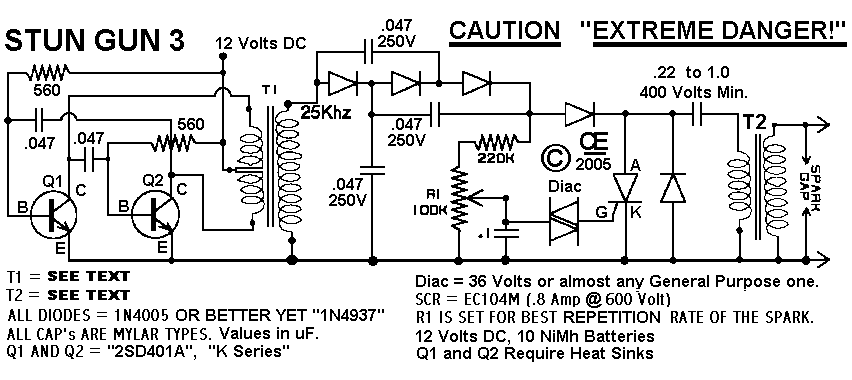
The Schematic. NOTE: The Actual Schematic Varies Somewhat from this Design! Like I Said, I didn't Intend this as an Actual Construction Article. But If your Good Enough to get the Transformers Right, and you have a good understanding of the Circuit You should be able to Complete it and make it operational.
T2 Verses the Spark Gap. There is A Direct Relationship here and it is Important.
 A Simple Tester to determine possible
Faults in T2 Transformers.