Updated: July 25, 2009
"Click Here to go Back to My Projects Page"
About this Circuit This is a good Circuit for those persons needing to Boost or drop a voltage. The Output is High Frequency, but can be Rectified and Filtered to give DC Out. When Rectifying High Frequencies, You MUST use the Appropriate types of HIGH SPEED Diodes to handle these frequencies. Normal diodes WILL OVERHEAT and Burn out.
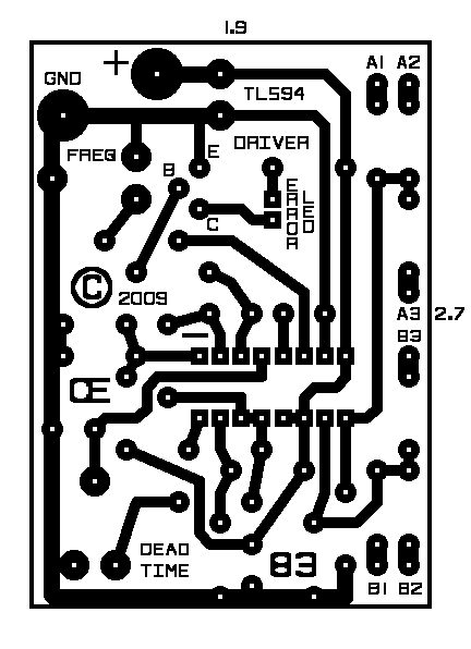
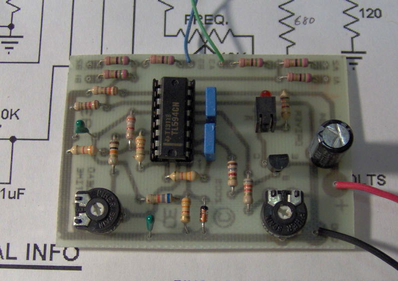
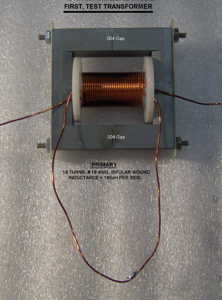
This Circuit is based on a TL594 Integrated Circuit. And I have designed it with an Auto Shutdown, If your 12 volt battery voltage goes too high or too low. This will help protect your Battery and Alternator. So if the LED is "ON", The "Circuit has Shut Down". It is capable of driving just 2 mosfets, or 4 (with 2 in parallel on each side), or 6 (with 3 in parallel on each side). So it can handle "LOTS OF POWER". The output voltage is determined by the "Turns Ratio" in Transformer "T1", as well as the Input voltage to T1. The TL594 Circuit Board Must have a Supply voltage of between 11 and 15 Volts. However, The Primary Supply Voltage for T1, Can also be 12 Volts, or Any other Voltage you want. The Primary winding should be "Bifular" wound, so both winding are identical. The Output Power can be Continuously Adjusted from very low to Full Power by using the "DEAD TIME CONTROL". If this circuit is Built According to the Schematic, the Frequency range will be aproximately 35Khz to 70Khz. About making the Transformer First Off, The Ferrite Core Material, MUST be Suitable for the "Frequency" and "Power requirements", of the transformer your attempting to make. Not all Ferrites are the same. The Advantage of using High Frequency is Less Turns per Volt, Resulting in Quite Small Ferrite core Transformers, as compared to 60 Hz, Iron Core Transformers. The Disadvantage is the need to use Smaller Wire as the Frequency Increases. WHY, Because the Higher the Frequency, the Greater the "Skin Effect". (The Higher the Frequency, The More the Current Flows on and near the Surface of the conductor.) To get Maximum Efficiency at 35 Khz, the Wire size should be a 21 AWG, But that is Only good for a Current of about 1.2 Amps To get Maximum Efficiency at 70 Khz, the Wire size should be a 24 AWG, But that is Only good for a Current of about 0.577 Amps. So to get High Current flow, at High Efficiency, you need to use "Litz Wire", or make your own, by Bundling numerous strands of an appropriate wire gauge. (Each Strand MUST be Insulated from each other, so Use Enameled Transformer Wire.) Since High Frequency Current Flows more on the Surface, It is also possible to use Flat Ribbon Wire. This type of wire offers consideraby more surface area in a smaller space. Such a wire may be only 0.010" thick, but 0.25 inch wide. And I believe that would be somewhat Equivalant to a 12 AWG, round wire and possibly efficient up to 10 amps. I can Supply the PCB and Associated parts. Possibly the Ferrite Cores Also, Just Depends on what your trying to do. More Transformer winding info Will be coming.
The Schematic
Than I Wound a Temporary Secondary over this for some output tests.
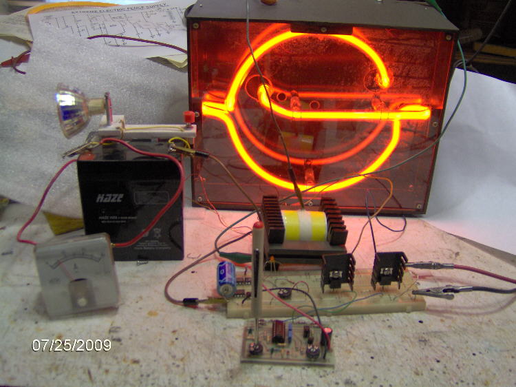
NOTE: These Heatsinks are Too Small and Overheat quickly.
Build and Use it this circuit your own risk!
"I Assume No Liability from the Construction or Use of this circuit"
All Imformation in this Article is "Copyright protected".
Chemelec
*Copyright © 2009*