A Few Relatively Simple "TENS" Circuits
Origonally Created in 2002. Latest Revision: February 24, 2018
I initially designed these circuits for a friend who had muscle problems and while he says: "they did work well for him", I "DO NOT" RECOMMEND THE USE OF THESE DEVICES BY ANYONE FOR ANY REASON. Never use these Tens Devices Above the Neck. I ACCEPT NO RESPONSIBILITY OR LIABILITY FROM THERE ASSEMBLY OR USE IN ANYWAY.
These circuit are to be used at Your OWN RISK. I "DO NOT" imply any medical benefit can be obtained from their use.
Some Background Info:
Tens machines are believed to provide a drug free way of removing pain and other things from your body. ( TENS stands for "Transcutaneous Electrical Nerve Stimulation". ) Frequencies in the range of 80 to 100 Hz. are believed to block the pain impulses going to the brain . Low frequency Tens use frequencies from 2 to 4 Hz .and are believed to help the body produce its own endorphins and increase local blood flow to relieve pain. ( Presumability, this effect can last for hours. ) Even Higher Frequencies in the khz range are believed to distroy certain Bacteria or Bugs in the body.
I am Not sure I believe any of this.
I RECOMMEND YOU GET A DOCTORS ADVICE, BEFORE CONSIDERING USING THESE DEVICES!
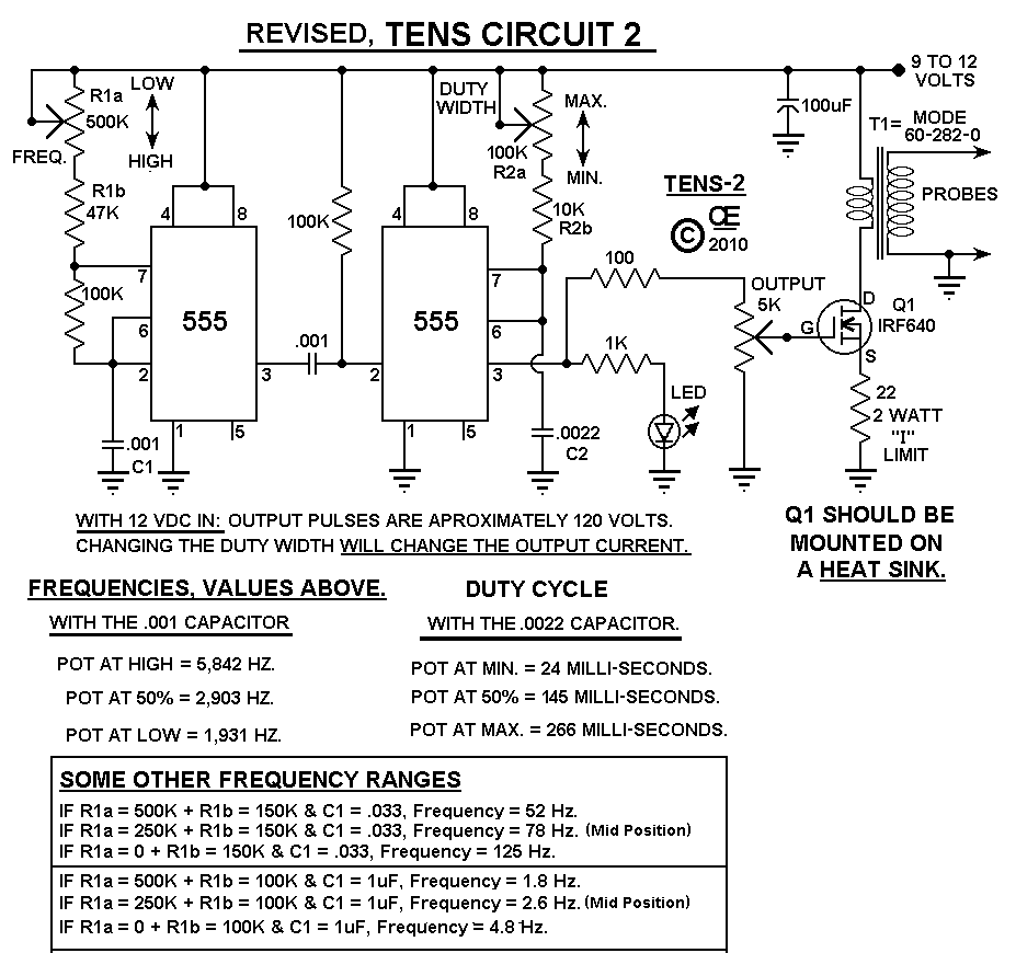
TEN's Circuits 1 and 2
I consider the TENs-2 as the Best and Most Versatile Circuit.
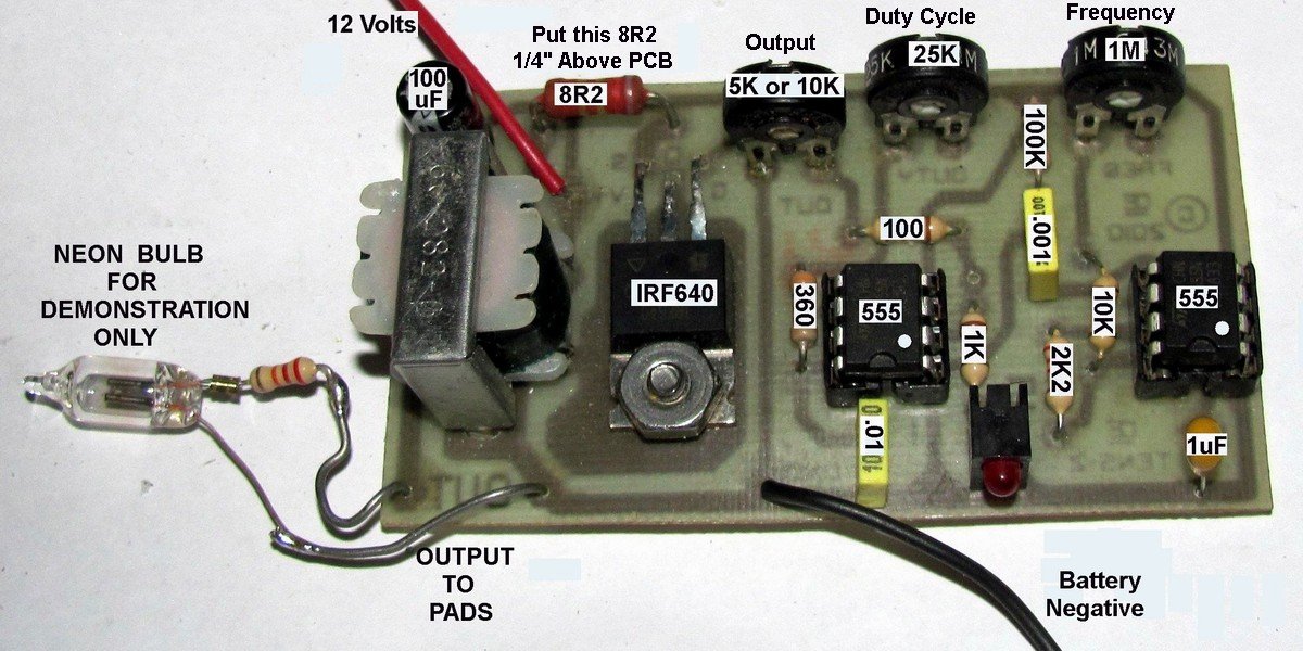
"T1" in Circuits "1 & 2" is a small audio transformer with the 8 ohm impedance winding connected to the Fet and the larger winding connected to the probe and ground. I Recommend using a "Mode" Transformer, Part Number 60-282-0.
The Turns ratio of the transformer determines voltage output.
A small 6 or 12 volt power transformer can also be used, But it will NOT give as good of an Output.
More
I Recommend using the Mosfet in Circuits 1 & 2, But a transistor such as a 2N3055 can be substituted for the "Mosfet".The Base connects to the Gate, the Collector to the Drain, and the Emitter to the Source. This change will result in a "Lower Power Output", but it still works.
The PCB for the Ten-1 also has provisions for a pot to control the Frequency of the 555. If you don't want to use this control, Just Short it out. If you do want this control, use a 1M or 2M Pot and Change R1 (2M2) to a 1M.
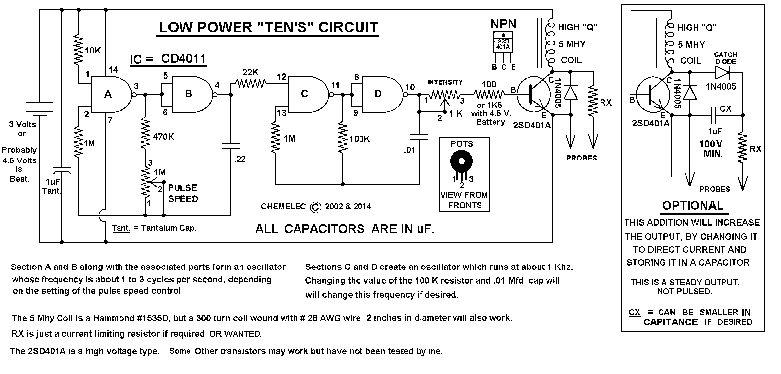
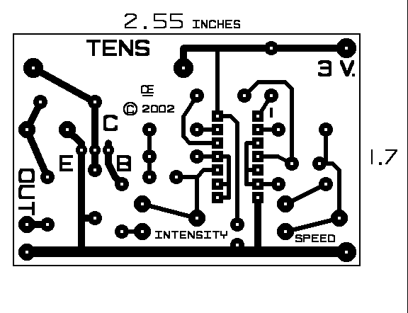
TEN's Circuit 3
Tens-3 is a very low powered, lower Battery Voltage Version, using a 5 mH Choke. (No transformer) It will light up an NE-2 bulb connected to the output, so it Exceeds 60 Volts Output. The Battery Voltage MUST be 3 Volts Minimum.
Probably Better is to Use 4.5 Volts. And with 4.5 Volts the 100 Ohm Resistor can be Increased to a 1K5 to give better Control on the Output.
For Informational purposes only: Their are also Low powered versions of these types of device are used by some Accupuncturists. Typically they are Just a 555 Oscillator, powered by a 9 Volt Battery and Without any Coil or Transformer. So the Output is Less than 9 Volts. This is NOT Enough voltage to Break through the Skin Resistance. So instead of pads, the signal is applied to the needles, giving a Very Localized Effect.
On All these TEN's Circuit, Different timing capacitors and resistors can be used for different effects.
Schematic of Circuits 1.
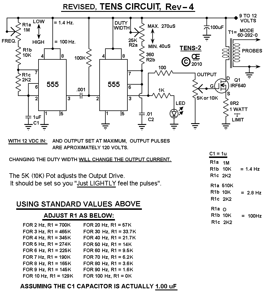
A Comment from one Person
Hi Gary, I have been checking specs on professional tens units and find the specs to be in the following range. Pulse frequency 2 - 120 Hz Pulse width 40 - 250 uS Is it possible to get any where near what the professional units specs are of 2-120Hz and pulse width 40-250uS, using your design assuming resistor capacitor values are changed. The current design appears to operate in the 2K - 6K HZ range. I was hoping to be able to come down in frequency using this design. Cheers, Victor
Here is the Schematic I Offered him.
And This is Probably the Best Version.
Chemelec
*Copyright © 2002 & 2014*