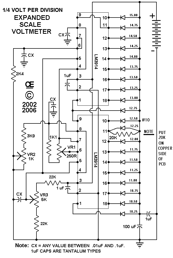
20 Segment Expanded Scale Voltmeter

Created "Nov 07 2002"
Revised "June 16 2009"

This is an Expanded Scale Voltmeter based on the National LM3914 chip.
It is a 0.25 volt range between each LED.

I specifically designed this unit for my spare battery in my RV Truck to continuously monitor its voltage. I did the orgional in a rush and have now changed a few values for ease of adjustment. Also added a few capacitors to corrected a few minor hum problems that affected some adjustments.

This Voltmeter it set for a range of: "10.25 to 15 volts".

The 20K resistor across the LED is required to null out the #10 LED. Leaving this resistor off will cause #10 to light Faintly when LED's above #10 are lit. This resistor is soldered to the copper side, due to space limitations!

Currently this unit is designed to operate from a 12 volt battery, over the range specified above. But it can be changed for Other Voltages and/or Ranges.


SETUP: 1) Set your supply Voltage to 12.500 Volts. 2) Trimpot VR1 is set to create a 1.200 volt drop between pins 4 and 6 on the adjacent LM3914. Test Point are provided on the board. This Must be set VERY ACCURATELY. 3) With the Supply Set Precisely at 12.500 volts Using Trimpot VR3, set the voltage at pin 5 of the LM3914's to 6.250 volts (both pin 5's are connected together) 4) Now Trimpot VR2 is adjusted to set the #10 LED to "JUST BARELY LIGHTING", (This occurs when Both 9 and 10 are Lit) Representing a voltage at midscale of the range. (Typical = 12.50 Volts) This is the LED marked #10 on the Schematic. The Full Scale should now be calibrated from 10.25 to 15 volts! Calibration Voltage Settings must be Very Precise with a good Digital meter..


SETUP-2 for Circuit 2, STILL TESTING AND STILL TO COME : This is for the Adjustable Voltage, Expanded Meter PCB. In this Example it is calibrated for an input between 11 to 30 Volts with a 1 Volt Resolution. Many Other ranges are Possible, 1) Connect Main 12 volt supply 2) Trimpot VR1 is set to create a 0.900 volt drop between pins 4 and 6 on the adjacent LM3914. Test Point are provided on the board. This Must be set VERY ACCURATELY. Why 0.900 Volts? There is a 9 Volt Difference between the Lowest LED and LED 10, And we want a 1 Volt Division between Each LED. NOW lets assume you want a scale from 11 Volts to 30 Volts. (20 LED's) (Top LED will = 30 Volts. Bottom LED will = 11 Volts) Number 10 LED will be 20 Volts. So set The Varying Input Supply for Precisely 20 Volts. 3) Now with an Input of Exactially 20.000 volts, Set VR3 to read 2.50 Volts on Pin 5 of the LM39124's (NOTE: Both Pin 5's are connected together) 4) Now adjust VR2 so that LED 10 JUST LIGHTS (LED's 9 and 10 will Both Lit.) 5) Lastly reset the input down below 11 volts and slowly increase it. a) The Lowest LED should now light up at 11 Volts. b) LED 10 Should light up at 20 Volts. c) And the Top LED should ligt up at 30 Volts. IF So, All is Correct. I HOPE.


Currently this circuit is designed to run in "Dot Mode" to reduce current consumption.

Breaking the trace between pin 9 and 11 on the top IC and connecting pin 9 to the supply rail will give a "Bar Display". "But as the bar length increases, SO DOES THE CURRENT, CONSIDERABLY".

PARTS AVAILABLE

I can supply the LED displays, listed in my parts area. Look at "LED's, Bar Displays" They are $1.50 each plus postage. All the other parts are available also. Postage cost on these parts depends on weight and where you live.

I can also supply the PCB for a Reasonable Price.

These prices are in US Funds.

"Back to My HOME Page"

 Revised Schematic NOTE: On Tantalum Caps, The Black line is Usually Positive.
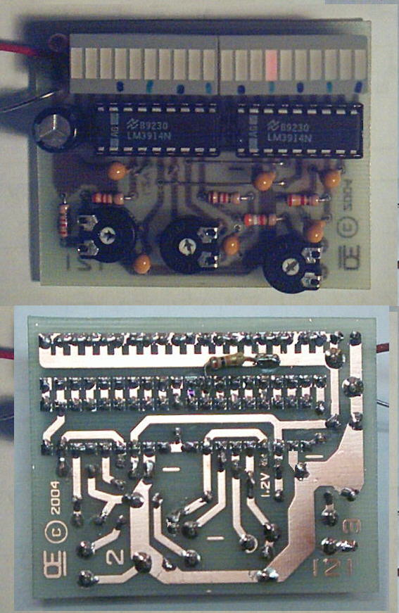
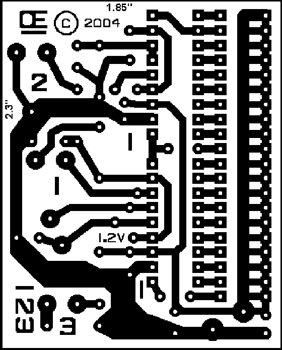
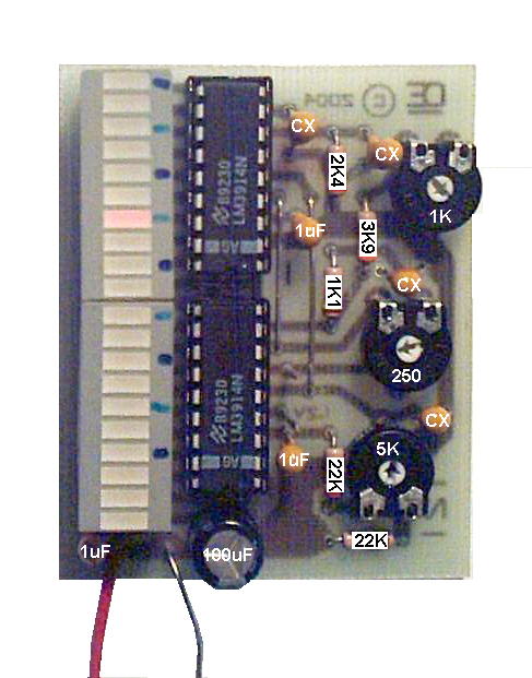
 Circuit Board A New and Better Image.

 Parts Overlay

All Imformation in this Article is "Copyright protected".

Chemelec

*Copyright © 2002 & 2006*