Simple Voltage Booster
The Circuit is Extremely Simple and is Useful for many Applications.
Created: "April 8 2005"
Updated April 11 2005, Schematic Error Corrected
Definately A Good Circuit for charging one battery from another.
But this application Requires a Additional Blocking Diode to prevent the Battery from Discharging through R1 and R2.
Both 22 uF Caps MUST BE Solid Tantalum Types, For Efficient Operation..
The Typical Circuit Efficiency is between 80% to 90%.
"L1": Needs to be able to handle the Maximum Current.
A Typical "Hash Filter" Type Choke of the correct Inductance, Usually works Quite Well.
Be aware the Output voltage is Always Greater than the Input Voltage.
It Cannot Be Adjusted Lower than that.
Typical Design Applications:
Considering the Maximum Input Current is 1.5 amps, and assuming 80% Efficiency.
1) If you want to boost 6 volts to 12 volts.
The Output Current at the 12 Volts will be about 600 mA.
2) If you are Charging one battery from another and only need to Boost the 12 volts to 14 volts.
Than you should get out about 1 Amp at the 14 volts.
"Back to My HOME Page"

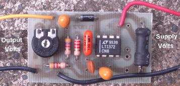
"A Picture of my Proto Board"
The Schematic For this Positive Boost Circuit
Enlarged View of Assembled PCB
There is an Optional Pull-up Resistor (1 Meg) and Standby Switch, Not Installed.
The Choke on this Proto Board is an 8.2 uH, Made by Miller. Works Good.
PCB
All Imformation in this Article is "Copyright protected".

 Chemelec  *Copyright © 2005*
