"Electric Fence, MORE POWERFUL Design"
"FENCER-2"Created: "Aug 10, 2009" Updated: "August 21, 2018"
IMPORTANT NOTE: Car Coil Fencers are NOT Suitable for LONG Fences.
A Fence having a Single wire and Shorter than 1 KM is probably OK,
If you have REALLY GOOD Insulators.
I Don't know why I didn't mention this Before, But if you want a HOTTER SPARK,
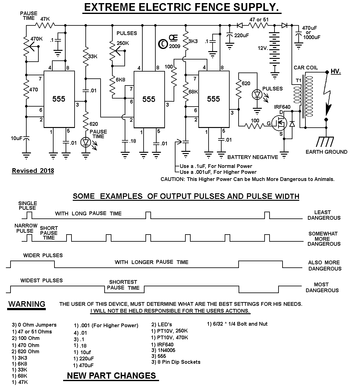
Replace the .1 cap on Pins 2 & 6 of the 3rd 555 with a .001
 "Hotter Picture overlay".
A circuit design to Drive a Car Ignition Coil with Single to Multiple Burst Pulses. With the Coil I use and set for the greatest pulse output, the Output is 22,000 Volts
This is a more complex Design than my C-Mos Electric Fence on my site. It also puts out Very high Voltage Current pulses, But in a Variabe Burst of current. The Variable BURST makes it More Powerful, But also More Dangerous. So USE this device WITH EXTREME CAUTION! With a Higher Burst, It will be Especially Dangerous to Smaller Animals.
"AVERAGE Current Draw" varies considerably, depending on pulse settings So a larger Battery may be required.
Note: Just Using a Battery Charger is NOT a Suitable Power Source
Also due to a High Peak Current Draw, this Fencer will NOT work properly,
just running from a Power Adapter or Lower Current, work-bench power supplies.
Some ADDITIONAL NOTES:
This Electric Fence Should be powered by a 12 Volt Battery and this battery
Should have a Trickle Charger on it.
A Small "100 mA Solar Panal" would probably do this quite well.
(Occassional Cycle Charging a car battery or Sealed lead acid Battery is not a good idea.)
THE CASE OF THE COIL SHOULD BE CONNECTED TO EITHER GROUND OR THE DIST. TERMINAL.
FAILURE TO DO SO, MAY RESULT IN THE CASE BECOMING ELECTRICALLY HOT.
On Some Ignition Coils, the Points Terminal is Marked as "Dist" for Distributor
and on some others it is marked as "Neg" or "-"
Also both the "Circuit Board and Coil Must be Protected from Rain and Snow".
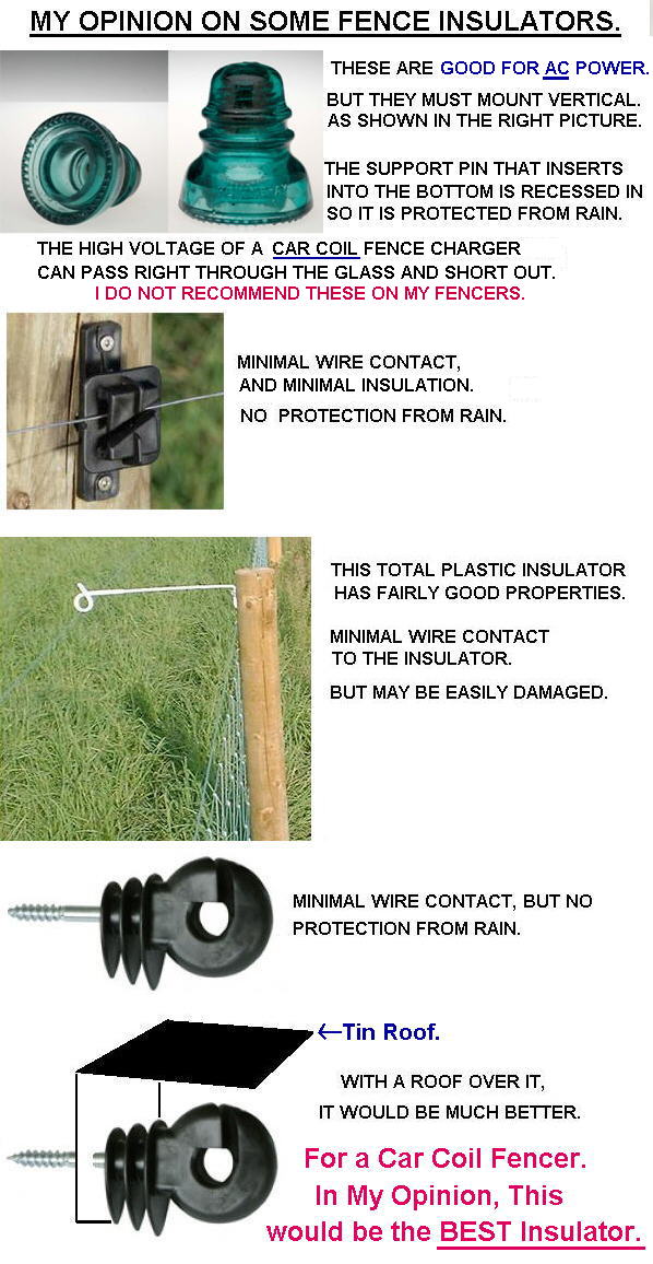
Suitable Insulators must be used on the fence, or Rain will short it out.
It Won't damage the circuit if that happens, But it also won't shock anything.
The Pause Control determines the OFF Time Between Pulses.
(Effectively, How many Pulses per Second.)
The Pause Time LED just shows its getting Power.
(Sorry, It Flashes to Fast to show the actual Pause time.)
The Pulse Control, Determines the Strength of the pulses.
(Effectively, Pulse Width.)
The Pulse LED, Basically shows the Firing of the Spark and Intensity.
After assembly of the Circuit board, All Solder Flux Should be Removed from it.
Solder Flux CAN Become Conductive in the presence of Moisture and this can
result in eventual failure. ESPECIALLY in an OUT DOOR ENVIROMENT!
Also both the "Circuit Board and Coil Must be Protected from "Moisture, Rain and Snow".
Suitable Insulators must be used on the fence, or Rain will short it out.
It Won't damage the circuit if that happens, But it also won't shock anything.
A Kit of parts/pcb is available from me. (Excludes the 12 volt Car Coil).
Also Not Included in the kit, But I Recommend adding a 1 Amp
Inline Fuse between the battery and this circuit.
It MUST be connected to a Suitable Battery for it to work properly.
Most Battery Chargers are NOT good DC POWER as they Contain a Lot of AC Ripple.


The Problem with Car Coils is their Extreme High Voltage.
And the Resulting Insulation Problems.
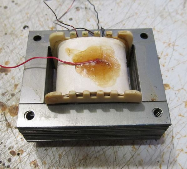
So Being Curious, I Built This Transformer.
Primary is 220 Turns of 24 AWG wire wound on 4 Layers, with insulation between layers.
Seconday is 4,755 Turns of 40 AWG Wire, wound on 10 Layers, with insulation between layers.
I Couldn't put more turns on this size of core.
The Output produces a 3/16 inch Spark and is Good for Smaller Animals.

The Schematic
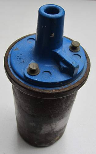
 This is the Type of Car Coil that is Required.

 "Picture overlay".
Note: Colors on parts you recieve in the kit, may be Different than shown here.
 Pictures from "DALE".
Some Pictures of a fencer-2 that this guy made.
All Imformation in this Article is "Copyright protected".
Chemelec
*Copyright © 2009 & 2018*